
In RC hobby signal inversion may be required when connecting various components together, i.e. RC receivers to helicopter flybarless units or other flight controllers. This is particularly often required in case of one wire protocols, like SBUS, PPM or Smart Port – the last one being specific to FrSky products.
IMPORTANT NOTE: READ AND UNDERSTAND AT LEAST THE “POWER SETUP” SECTION. Wrong power setup may cause damage to all connected devices. If unsure, ask in the comments at the bottom of the page.
In some cases it is possible to get uninverted signal by soldering directly to the PCB of the receiver. In other cases it is possible to invert the signal in the firmware of flybarless unit or flight controller. If these options are for whatever reasons not available, the only solution is to use external inverter.
Different vendors are offering they own, ready to use inverters, i.e. MSH51645 in case of Brain / Ikon, FrSky Integration Cable in case of Spirit Systems, various inverters available elsewhere.
It is very simple and fun to build own signal inverter, which will also save few bucks in comparison to commercial ones.
MAK RC Signal Inverter is based on specialized Schmitt trigger inverter chip, which is in fact doing all the job. The advantage of Schmitt trigger based inverter is its reliability, quality of re-produced signal and negligible added latency.
Gallery


Proof of Concept
Features
- Universal usage, various power options
- Excellent quality of the inverted signal (inversion performed by Schmitt trigger inverter chip)
- Dimensions 8x18mm
- Negligible latency
- Accepted voltage range 1.65V ~ 5.5V
- Tiny, SMD based design, but large enough for manual soldering (0805 and SOT-23 components)
- Inexpensive and easy to build, using widely available components
What is signal inversion?
Signal inversion is simply taking original, source signal and reverting it, so i.e. where in a point in time there is 0V, it should be 3.3V instead and where is 3.3V, it should be 0V. Level of 3.3V is just an example (commonly used though) of voltage level representing logical true in digital protocols, in opposite to 0V representing logical false.
Altrough PWM and PPM are not digital protocols per se, but due to its nature Schmitt trigger inverter can be use to reverse their signal as well.
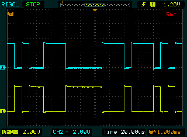
The below picture shows original SBUS signal (channel 1, yellow) and its inverted version (channel 2, blue):
How to build own inverter?
- Download Gerber files (download link below). Upload them to one of Printed Circuit Board (PCB) manufacturing sites and order ready to use PCBs. You can quickly check offers from many popular manufacturing sites using PCBShopper.com – I usually use JLCPCB.com. Ordering PCBs is inexpensive, but delivery may be even more expensive. Thus it make sense to share the order with few friends.
- Check the below Bill of Materials and order required electronic components (all three of them). Popular sites you can get electronic components from are RS Online, Digikey. They both have local stores all over the world and can deliver any components in a matter of days.
- Solder components to the PCB. Soldering small SMD components may seem to be challanging, but it really isn’t. Just search for “soldering SMD” on YouTube (click the link to take you right there). You will need reasonably decent soldering station, solder flux paste and 0.3-0.6 mm solder wire though.
- Before soldering cables to the PCB read the below section about power setup. Always solder ground and IN / OUT signal cables, but choose carefully how to power the inverter (which power wires to solder to the PCB).
- Crimp required wire connectors or solder directly to receiver / heli flybarless unit / flight controller. You may need special crimping tool to make connectors properly. I use Engineer PA-09 Micro Connector Crimper, which I absolutely love and which is far the best compared to anything else I was using before.
- Voila :).
Bill of Materials
| Component | Value / Model | Package type | |
| U1 | Schmitt trigger inverter | SN74LVC1G14DBVRE4 | SOT-23 5-pin |
| R1 | Resistor | 47K | SMD 0805 |
| C1 | Ceramic capacitor | 80-100nF, 10V or more | SMD 0805 |
Cost
Assuming you will order few of them, cost of all parts for single, complete inverter is around US$1. This is excluding delivery – which can be as low as zero, depending from where do you order and how long you are willing to wait.
As I wrote above, it make sense to order a bit more PCBs and components and share its and delivery costs with few friends. For sure every one of you will need 5-10 inverters :).
Power setup
The inverter is a very simple device. However due to the nature of how Schmitt trigger chip works and because the inverter has no internal voltage stabiliser, it is EXTREMELY important to power the inverter in a proper way.
The inverter chip replicates original signal (of course inverted), but also changing its voltage level proportionally to its own power source. In most of the RC receivers – even if they are powered from 5V, 6V or 8.4V – the output level of signal wire is kept at 3.3V max. Higher signal voltage level would probably damage connected heli flybarless unit or flight controller.
It is important to understand and differentiate between general power voltage and signal voltage levela. In example MSH Brain 2 can be powered by 8.4V 2S LiPo battery, but still it expects 3.3V signal voltage levels on its SAT-1 and SAT-2 ports (and it is providing 3.3V power on these ports).
Note that the inverter itself will accept 5.5V max voltage. Thus the inverter cannot be powered from 6V nor 8.4V (i.e. directly from 2S LiPo), even if by some miracle 8.4V would be acceptable level of signal voltage level of connected heli flybarless unit or flight controller.
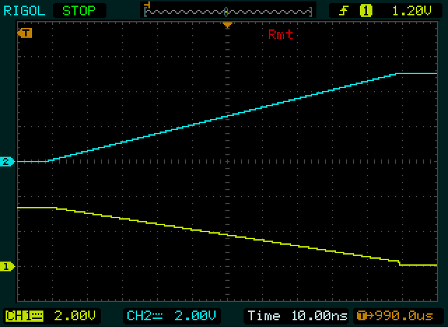
On the below picture the signal level and the power voltage level are equal (at 3.3V), so the inverted output signal is also capped at 3.3V level:
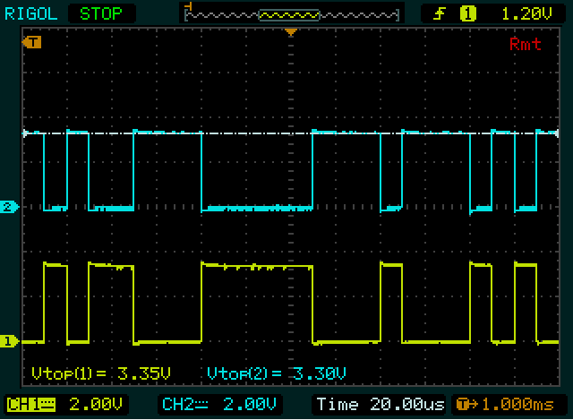
Please note that every one vertical division (marked with dotted, grey lines on the graph) represents 2V. In addition average top voltage levels are provided as Vtop measurements at the bottom of the screen.
As you can see, the input voltage level (channel 1, yellow) is 3.35V (it is close enough to 3.3V) and output signal (channel 2, blue) is the same 3.3V level. This is considered as a safe setup.
On the below picture we can see different situation. Input signal is 3.3V, but inverted output is at 5V level (4.98V):
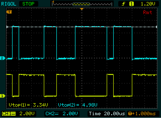
This setup could be a potential problem if receiving device (usually heli flybarless unit or other flight controller) cannot accept 5V signal level (usually because it is expecting 3.3V, due to its own internal power source stabilized at this very level).
Taking into consideration all above, it is important to power the inverter with a voltage, which will produce safe level of the output signal voltage.
The power source for the inverter can be provided from input, output, both sides or from external source.
Note: in any case input signal voltage level should NOT exceed the inverter power voltage level, so i.e. if the inverter is powered from 3.3V, the input signal level should not be 5V (or anything higher than 3.3V in this matter).
Scenario 1: power from OUTPUT
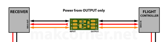
This is most typical and most safe scenario. The inverter is powered from its OUTPUT side, typically from 3.3V (i.e. MSH Brain’s SAT-1 port). To achieve that, the power (+) wire should be soldered from from OUTPUT side only. The power (+) wire from INPUT side should NOT be connected (not soldered to the PCB of the inverter).
This scenario is typical to connect FrSky receivers to SAT-1 port of MSH Brain / Ikon flybarless units, when using FrSky / OpenTX receiver type in Brain / Ikon setup.
IMPORTANT NOTE: both SAT ports of Brain / Ikon do NOT have positive wire in the middle of its JST ZH plug. Negative GND wire is in the middle instead. Please refer to the above pictures.
Scenario 2: power from INPUT
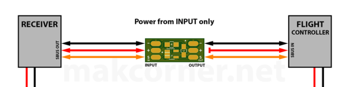
In this scenario the inverter will be powered from INPUT side only, via its power (+) wire. The power (+) wire on the OUTPUT side must NOT be connected to the inverter.
The output signal voltage level will be determined by power level connected to INPUT side (+) wire.
If the input power voltage is 3.3V, usually there is no issue. However – if the power voltage level of the inverter will be 5V – it will produce the same voltage level on inverted output signal, even if original signal voltage level would be 3.3V. This could potentially damage the controller unit connected to OUTPUT side.
Scenario 3: power from both INPUT and OUTPUT
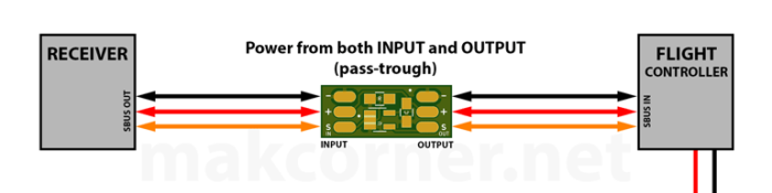
In this scenario power (+) wires of both INPUT and OUTPUT sides are connected to the inverter.
Such a setup can be useful if the output signal voltage level can be accepted by connected controller unit and if we want to power the receiver from the controller unit via the inverter (as on the above picture), or opposite, if we want to power the controller unit from the receiver.
The inverter can be considered here as a pass-through power device. The inverter can be powered from either side, and in the same time, the other device (not providing power to the system), will be powered via the inverter.
As in scenario 2, output signal voltage level will be equal to inverter’s power voltage level. Use this setup only if you are certain that connected output device can accept this voltage level.
Note: as the inverter is a tiny device, its PCB traces cannot handle excessive current. Any current in a 100-300mA range should be fine, but I wouldn’t recommend to stress it more. Test it in any case before flying.
Scenario 4: power from EXTERNAL source
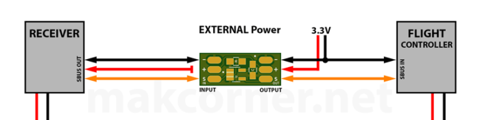
In this scenario usually we will want the inverter to be powered from external, stabilised voltage source only (usually 3.3V), to produce inverted output signal with safe, 3.3V voltage level. Both input (typically RC receiver) and output (typically heli flybarless / flight controller unit) are powered independently, i.e. from 5V or 8.4V power source, and both power (+) wires should be disconnected from the inverter.
Last notes on power setup
There are other possible connection combinations or solutions which can be used to deliver inverted signal with acceptable voltage level, i.e. using 3.3V Zener diode to cap output signal voltage level.
Important is to choose power setup knowingly and intentionally, keeping in mind acceptable signal voltage level of the device connected to the output of the inverter. Almost all devices can accept 3.3V logical signal voltage levels and this should be always your assumption if unsure.
Also please note that the inverter itself can accept power voltage up to 5.5V, so do not connect 2S LiPo battery directly.
Always connect together GND pads / wires of all devices that are inter-connected.
Latency
Schmitt trigger inverter is not introducing virtually any latency.
The below picture is a close magnification of the falling edge and its corresponding (inverted), rising edge of SBUS signal:
As can be seen above, even with time division set to 10ns, it is hardly possible to recognise any latency between the channels.
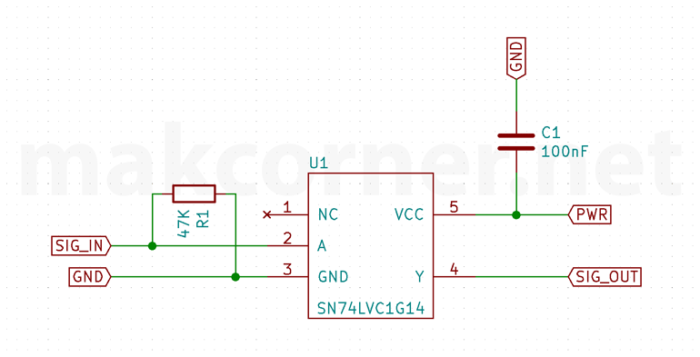
Schematic
For those who would like to build the inverter, but without using my PCB, here is an electrical schematic:
Downloads
License & Legal disclaimer

This work is licensed under a Creative Commons Attribution-NonCommercial-ShareAlike 4.0 International License.
The project is tested and it worked for me. However there is absolutely no guarantee nor liability behind – use on your own risk and responsibility.
Feedback
Would love to hear your feedback on this project. Let me know if you have build one. Do not hesitate to ask questions if you have any.
Particularly please let me know if it would make sense to design an extended version of the inverter, with output signal voltage level stabilized at 3.3V.
Please leave your comments and questions below.
First of all – the inverter got me into smd soldering successfully – and it works like a charm – thanks a lot for sharing your knowledge and work – Theo
I have one issue that needs to be solved which is outlined here:
https://discuss.ardupilot.org/t/sbus-amplitude-pixracerr15-ardurover-4-4-too-low-for-frsky-sbus-pwm-encoder/111983
Any suggestions are more than wellcome.
Regards,
Theo
The inverter got me into smd soldering successfully and it works like a charm. Thanks for sharing your knowledge. Theo