

The OpenTX offers almost unlimited possibilities for configuring RC models. This article covers a detailed and quite advanced OpenTX configuration for a nitro helicopter, operating under control of MSH Brain 2 flybarless unit.
This article was originally published in Polish, on the 77Hobby Forum – FrSky Premier Dealer and the OpenTX evangelist.
This English translation is based on automated Google translation. I did some manual corrections, but – due to time constrains – it was just to correct the most obvious issues. Thus please do not expect Shakespeare English here, but I hope it is still usable.
Download
Here you can download OpenTX Configuration and voice files used in this article:
Config file should be opened in OpenTX Companion, using Horus X12S profile (it can be then easily converted to any different radio, simply by changing the profile in the Companion).
Voice files should be uploaded on SD card, into SOUNDS folder of the language you use (i.e. \SOUNDS\en, \SOUNDS\pl, etc.). If you want the voice files to work properly in OpenTX Companion simulator, they must be uploaded into SD card image structure defined for Companion simulator.
Introduction
If you are just starting an adventure with OpenTX, I recommend reading the article What is the OpenTX?
The aim of the article is to present – using the example of a rather technically complicated model – a complete configuration of the nitro helicopter in OpenTX. At the same time, the intention is also to show the possibilities and potential of OpenTX. Therefore, I will deliberately try to use as many tools and different configuration methods to present as much as possible of what OpenTX offers. Many of the shown functionalities can be set up in OpenTX in different ways. I tried to choose methods, which allow me to “smuggle” a bit of general knowledge about OpenTX. For the same reason, some elements that are not so often used in the RC model daily practice (i.e. heli tail-free mode), will be configured and described.
The description below – probably with minor modifications – will be adequate for any other model of nitro helicopter. In the great majority it will also be useful when configuring electric helicopters or any other RC model. Examples of triggering of counters, setting up alarms, special functions, flight modes, configuring the mixer, handling global variables, etc. are universal.
I assume that the reader has a basic knowledge of RC model hobby, OpenTX configuration and is familiar with the specific and technical aspects of RC hobby as such. Knowledge about RC helicopters will be helpful. Nevertheless, the article is quite extensive and I explain many things from scratch.
I will present the OpenTX configuration in OpenTX Companion, thanks to which it will look very similar, no matter which FrSky radio you own. I will be using the profile for the FrSky Horus X12S radio, but it does not matter much. This configuration will work on any OpenTX, although it may be necessary to adapt to a given radio model, or more precisely to the number, type and names of switches / potentiometers (without any changes it works on X10 / X10S and X9D; QX7 does not have SG switch, so it requires re-mapping this particular switch.
I will use OpenTX 2.2.3, which is also of little importance. I have not tested this, but the configuration should also work well under the OpenTX 2.1 series without major changes.
The test radio is set in MODE 2, which is relevant only when further referenced in the text to the right or left stick.
In the further part of the text I often refer to the state of switches of FrSky radios. They are marked with capital letters SA, SB, SC, SD, SE, etc. Amount of switches vary per radio model. Switches can be three-position (towards ↓, middle position -, away ↑) or two positions (towards ↓, away ↑). For example, the entry “SC-” means the middle position of the SC switch, and the entry “SF↑” indicates away position. I refer to the items “towards” and “away” to the situation when the radio is normally used (i.e. kept in hands or hung on a neck strap, directed with its antenna towards the controlled model).
All photos and drawings in this article are thumbnails. Click on the thumbnail to view the full resolution image.
Project assumptions
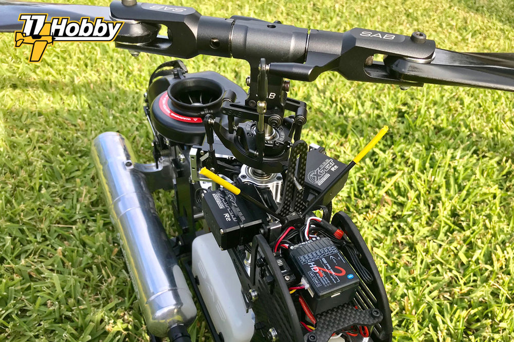
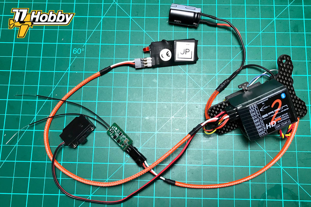
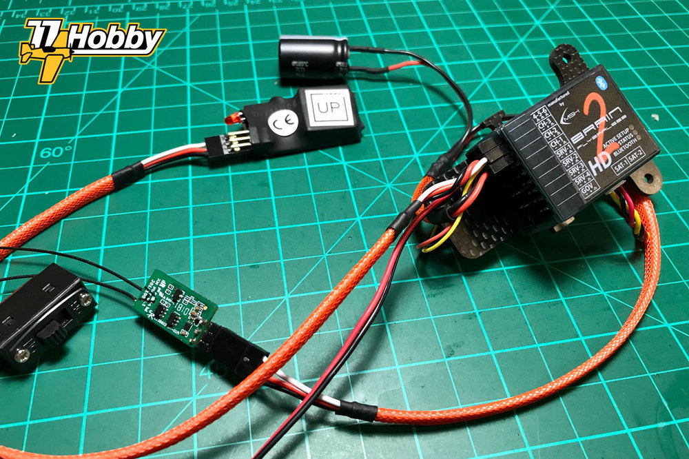
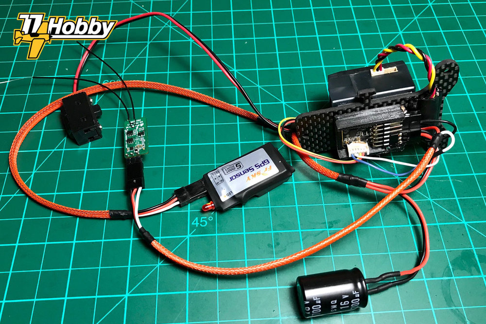
An exemplary helicopter is a real, existing and flown model. All described functionalities have been checked and work correctly (however, please check the disclaimer note at the end of the article).
The model is equipped with the following remote control electronics:
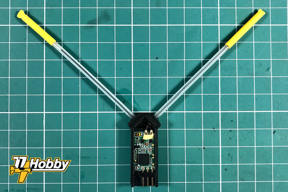
- FrSky RX4R receiver
- FrSky XM+ redundant receiver
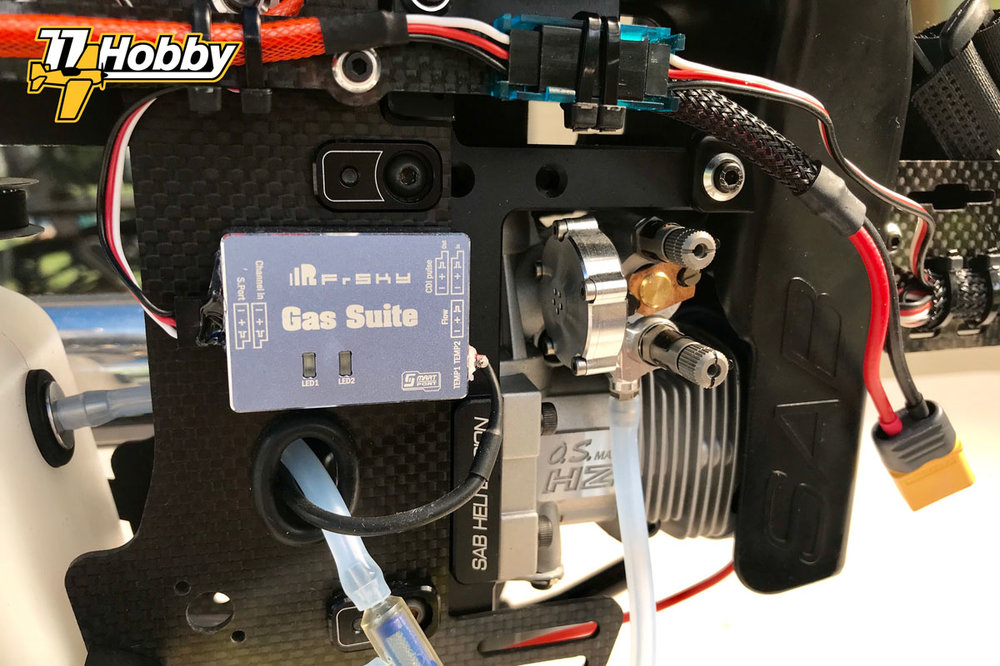
- FrSky Gas Suite telemetry sensor with PT1 temperature probe
- FrSky GPS v2 telemetry sensor
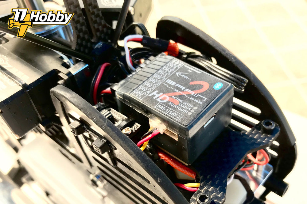
- Flybarless controller MSH Brain 2 BT HD (hereinafter referred to as FBL controller or simply FBL; Brain controllers also appear under another trade name – Ikon).
- MSH51645 signal inverter
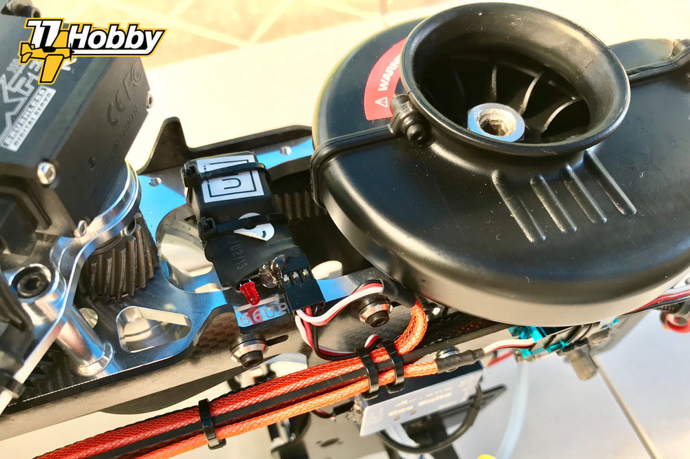
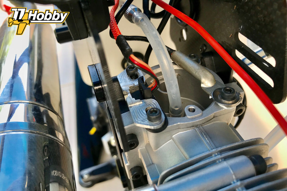
- engine RPM sensor SPMA9569 spectrum, type “backplate”, which generates pulses on the basis of crankshaft rotations, through the rear cover of the nitro engine (the sensor is connected to the Brain 2 controller)

Radion Control link
I used eight RC channels for helicopter control, in default Brain 2 order:
- CH1: Ailerons (shuttlecocks)
- CH2: Elevator (elevator)
- CH3: Throttle (throttle)
- CH4: Rudder / Tail (rudder)
- CH5: Tail Gain (P gain for tail rotor PID controller)
- CH6: Pitch (general inclination of main rotor blades)
- CH7: Setup (flight modes)
- CH8: Aux (used to activate the so-called “rescue”, ie the emergency mode of self-leveling the model)
(in the terminology of helicopter modeling Ailerons and Elevator are referred to collectively as Cyclic, and Rudder as Tail).
The values of control channels of the RX4R receiver are transferred via the SBUS OUT port (one cable only), connected via the MSH51645 inverter to the SAT-1 input of the Brain 2 controller, according to the following diagram:

Brain 2 on the SAT-1 port waits for an unrecorded SBUS signal. FrSky uses the inverted signal on the SBUS outputs of its receivers. To adjust the receiver’s SBUS signal to the expectations of the Brain 2 controller, it must be reversed again using the MSH51645 signal inverter (double inversion gives the original SBUS signal).
Instead of using a signal inverter, you can modify the receiver in such a way as to connect to the SBUS signal before it is inverted and fed to the standard SBUS output of the receiver. To achieve this, you need to solder in the right place on the PCB of the receiver. However, this eliminates the need for the MSH51645 inverter. In the case of the RX4R receiver, connecting to the correct pin on the PCB is technically demanding, due to the large scale of miniaturisation of the RX4R receiver. Soldering to the correct pin is not easy, although possible with a little practice and using the right tools (connecting to an un-inverted SBUS signal is much easier in such receivers as FrSky X4RSB, R-XSR, XSR-M, XM+ and others).
ATTENTION: When using a modified receiver or other signal inverter, remember to not connect power to the SAT-1 port of the Brain 2 controller (there is another, separated supply voltage level on the SAT-1 port power supply pin). Probably for this reason, the original MSH51645 inverter also does not carry the power line, it is by default disconnected on the MSH51546 inverter PCB. In addition, the pin spacing of the SAT-1 port is not standard, i.e. the power pin is not a middle pin (just like popular JR type model plugs) – pay special attention when preparing the plug connected to the SAT-1 input of the Brain 2 controller.
Redundancy of the RC link
The RX4R receiver enables connection of a second, spare receiver, from which the control signal will be taken, in the case of loss of coverage by RX4R own antennas. In the case of helicopter models, the use of an additional receiver may be of particular importance, since the construction of a helicopter – usually mainly of carbon fiber, with a large number of metal and closely spaced components – can effectively block the radio signal in certain positions of the model relative to the transmitter.
To use a redundant configuration, the SBUS (OUT) output of the backup receiver connects to the SBUS (IN) input port of the master receiver. Both receivers bind to the same model in the radio – a master receiver with telemetry support, a backup receiver without telemetry. FrSky XM+ is an ideal backup receiver due to ultra-miniature size and no telemetry support. It is also very inexpensive choice.
The master receiver antennas (RX4R) are located under the rotor head, maintaining a 90° angle between individual antennas. The backup receiver (XM+) antennas are located under the tail of the helicopter. This arrangement of antennas should ensure excellent RC signal reception, regardless of the position of the model.
…to be completed: the wiring diagram of all elements
Power
All electrical components used in the model can accept HV (High Voltage) power, up to 8.4V. As a result, the model’s electrical installation can be powered directly from the LiPo 2S battery, bypassing the voltage stabilizing system, so-called BEC or SBEC (depending on the design, linear or switching stabilizers, respectively).
Direct power supply from the 2S LiPo battery eliminates the potential failure point (BEC / SBEC is one of the most frequent failures) and unwanted radio interference (SBEC power inverters often introduce radio noise). Direct power supply offers virtually unlimited current efficiency (usually more than necessary to power even the most powerful digital servers), and also allows easy reading of the model’s power supply voltage and transmission of this information in the telemetry system (more on this later in the article).
In the example model, the helicopter mechanics is driven by a nitro engine, which does not require separate power supply (no ignition system). You can mount the on-board glow system. It is not necessary, although certainly very convenient.
In the absence of BEC, this is not required, but just in case, a 4700μF capacitor has been connected to the power supply circuit, the task of which is to filter out any sudden voltage drops.
Telemetry
One of the advantages of OpenTX is its advanced telemetry system. An example of the configuration of the telemetry system in OpenTX 2.1 and newer is described in the article Telemetry OpenTX 2.1 .
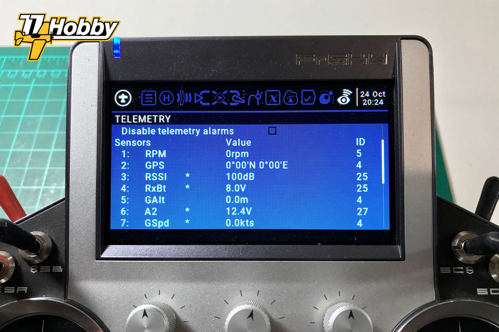
The following telemetric sensors (parameters) are used in the example model:
Read directly from the receiver
- RxBt – supply voltage of the receiver, in this case identical with the supply voltage of the entire electrical installation of the model
- RSSI (Received Signal Strength Indicator) – level indicator of the received RC signal
Read from the FrSky GPS v2 sensor
- GPS – GPS coordinates
- GSpd – horizontal speed relative to the ground
- GAlt – altitude relative to sea level (modified to show height relative to the starting point)
- Date – current time and date
Read from the FrSky Gas Suite sensor
- GTp1 – engine temperature, measured on the rear plate of the OS 105HZ-R engine (the gas flow sensor is not used, as the fuel level in the tank is clearly visible in sport helicopters).
Read from the Brain 2 controller
- RPM – rotational speed of the main rotor
The values of individual telemetric parameters are read by the Smart Port of the RX4R receiver, sent back to the transmitter and used in OpenTX, e.g. for setting alarms.
All Smart Port sensors – also the Brain 2 controller used in this role – are connected to the same Smart Port bus. More details about the different types of ports used in FrSky and modeling in general are in the article RC Ports not only FrSky .
Thanks to the fact that the Brain 2 can communicate with the FrSky Smart Port receivers, it is possible to read a very important parameter – rotational speed of the main rotor of the helicopter (RPM sensor). In this configuration, this parameter is logged in OpenTX and it is possible to read its current value in voice, which is very useful in flight mode without an active governor.
Configuration of the MSH Brain 2 (Ikon 2) flybarless controller
In this article I use the Brain 2 flybarless controller (also sold as Ikon 2), but the OpenTX configuration will be similar to any other FBL controller with built-in motor governor control module (so-called governor). The main differences with another FBL controller will probably be related to the number and / or order of the channels used to control the model and the functions of the FBL controller used.
The purpose of the article is not to describe the configuration of the flybarless MSH Brain 2 controllers, but to understand the rest of the article it is necessary to provide at least basic information about how the FBL controller was configured.
I will also try to put in more information useful for configuring Brain 2 / Ikon 2 controllers from time to time.
Provided information will mostly apply to the first versions of Brain / Ikon controllers (from the configuration page version 1 does not differ significantly from version 2).
Basic information about Brain 2 flybarless controller configuration
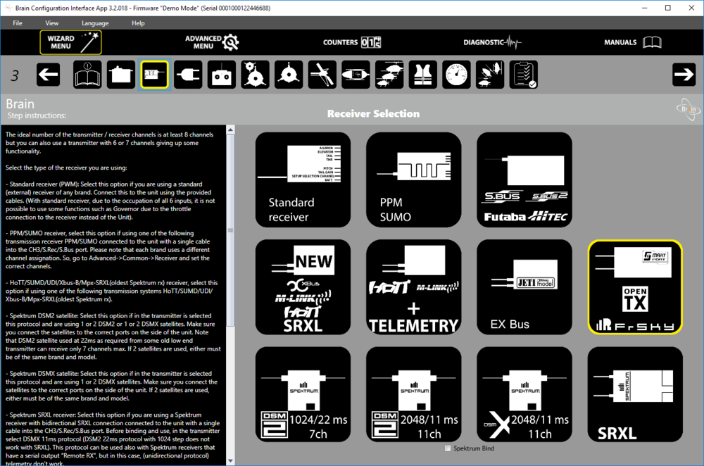
“Smart Port / OpenTX / FrSky” was selected in the selection menu of the receiver type.
Three flight modes (styles) have been defined, selected by the CH7 channel:
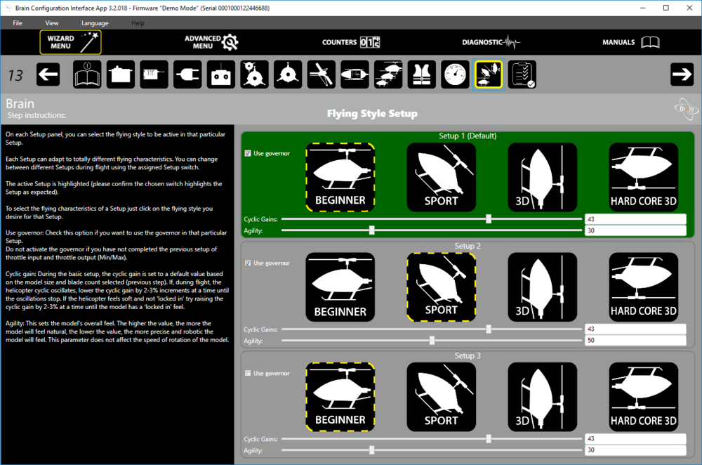
- Normal (active governor, parameters for quiet flying or for beginners)
- Sport (active governor, parameters for flying sport or even aerobatic 3D)
- Normal without governor (nitro lapping mode or in case the RPM sensor fails to connect to Brain 2 governor)
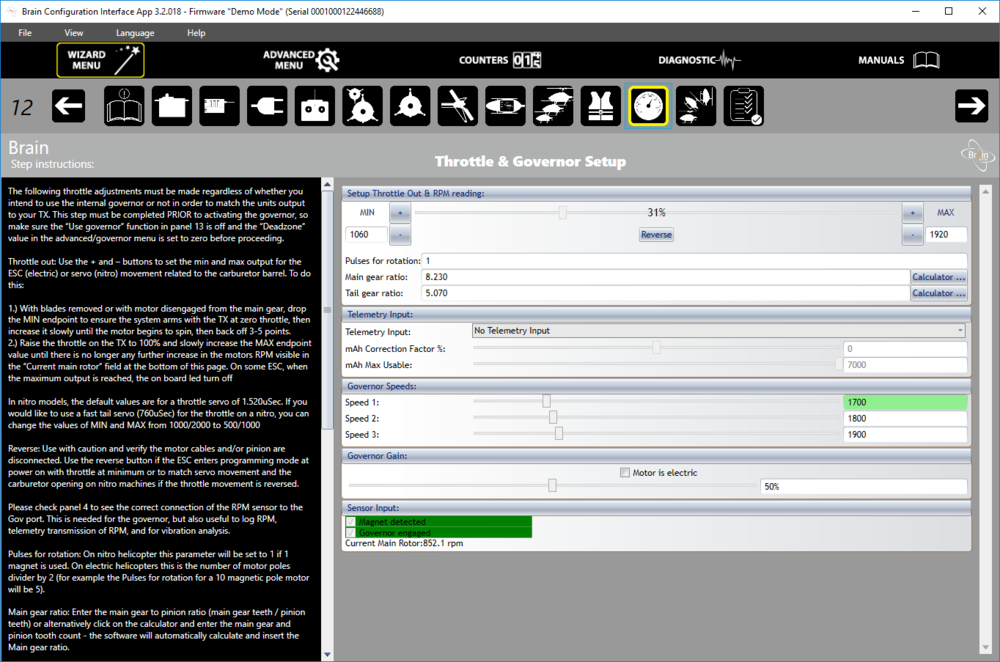
Governor is active only in Normal and Sport modes. Target governor revolutions in these modes are controlled by the Throttle channel level (CH3), according to the Brain 2 documentation:
- 0-24% – without governor
- 25-49% – speed 1 (40% recommended)
- 50-74% – speed 2 (Speed 2, 60% recommended)
- 75-100% – speed 3 (Speed 3, 85% recommended)
NOTE: Brain 2 – and probably many other FBL controllers – refers here to percentages in the 0-100% range. FrSky uses the range from -100% to +100%. The values should therefore be appropriately recalculated.

The conversion can be done using the below formula, assuming:
X – range from -100% to +100%
Y – range from 0% to 100%
The formula for conversion:
X = Y - 100 + Y
e.g. for recommended 40% of Throttle values on a scale from 0-100%:
X = 40 – 100 + 40
X = -20
Thus, in the OpenTX configuration, to activate the Speed 1 Governor Brain 2 mode, use a minus 20% value (or other, calculated according to the above formula, corresponding to the required range of 25-49% on a scale of 0-100%).
In practice, this value can be selected experimentally, observing what value shows the Brain 2 configuration program (Brain 2 channel monitor in the Transmitter Setup tab).
… returning to the Brain 2 controller configuration:
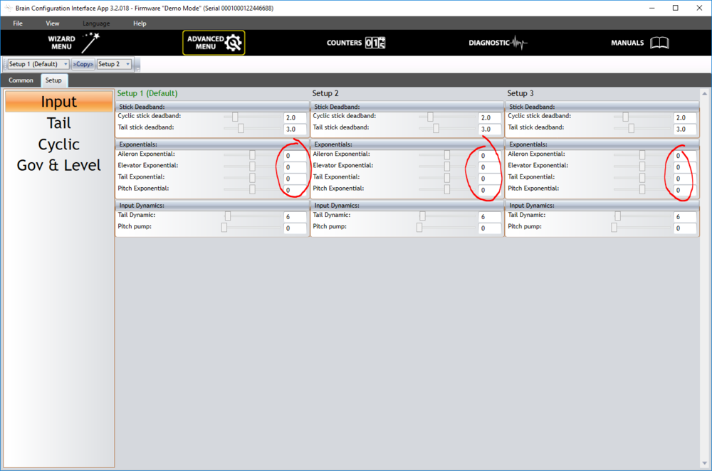
The expotential values for both cyclic, tail and pitch in the Brain 2 controller are set to zero. Their values are defined in OpenTX. This allows you to easily change these parameters from the radio without having to connect to the FBL controller via Bluetooth or USB.
From the point of view of the article, it is also important to configure the “Rescue” and “Tail gain” functions:
The “Rescue” function (emergency self-leveling of the model) is activated by the Aux channel (CH8).
The CH5 channel value defines the so-called “Tail gain”, so gain of the proportional (P) part of the PID controller implemented in FBL unit, controlling the pitch of the tail rotor. Positive values of the CH5 channel determine the gain in the heading lock mode and the negative values in the “tail free” mode (as it is easy to see here, the Brain 2 configuration uses a full scale, from -100% to +100%).
Of course, the configuration of Brain 2 controllers is much more complex. However, the other options do not affect the OpenTX configuration, yet the subject of this study is not the FBL configuration. Therefore, we will not delve into the other configuration parameters of the Brain 2 controller.
Supported functionalities
Before proceeding to the detailed description of the implementation, I will describe what functionalities will be assigned to individual switches and potentiometers of the RC radio.
Of course, given below, specific switches have been chosen only on the basis of personal preferences. In OpenTX you can assign any switch (or potentiometer) to any function.
SF switch – so called “Kill-Switch”
All RC models can be potentially dangerous. Kill-Switch – a safety switch – should be part of the configuration of every larger model.
SF↓ results in an unconditional shutdown of the motor (regardless of the positions of other switches). In the case of a nitro engine, this is accomplished by completely closing the throttle.
SF↑ causes “arming the engine” – in the case of a nitro engine, the throttle is moved to the idle position.
Note: The SF switch – as the only one in our setup – is active in SF↑ position (so it triggers, “arming” the motor, in the switch position away from yourself, while all other switches are active in ↓ position). Active SF↑ position ensures additional safety when operating the model, i.e. when putting the radio on the ground and accidentally hitting active switch SF↑, it will be pushed into SF↓, effectively killing the engine (as an opposite to spooling it up).
SA switch – Throttle-Hold / Spool-Up
In the SA↓ position, the Throttle channel (CH3) changes its value, to spool-up the engine.
In any other position (SA↑, SA-), the engine runs at idle speed, so-called Throttle-Hold. The idling level can be adjusted using Throttle trim, but only if the SA switch is in the Throttle-Hold positions (changing the idle level during flight is inactive to avoid accidental corrections of the idle level).
SB switch – Idle-Up
The individual positions of the switch (SB↑, SB-, SB↓) correspond to the three engine speed levels set in the governor of the Brain 2 controller (if the governor is active).
SC switch – Flight Modes
The individual positions of the switch (SC↑, SC-, SC↓) correspond to the three flight modes (styles) defined in the Brain 2 controller. The third mode assumes no governor and thus throttle control using the traditional throttle curve.
SD switch – Heading Lock
In the positions SD↑ and SD- the FBL controller operates in the so-called Heading Lock mode, so maintaining fixed yaw of the model.
In position SD↓ the tail boom of the helicopter is “released” (so called Tail Free or Rate Mode), so the helicopter yaw is affected by the influence of aerodynamic forces acting on the model.
SH – Rescue switch
In the SH↓ position, the “Rescue” function of the Brain 2 controller is activated, trigerring emergency self-leveling of the helicopter.
Note: SH is a momentary switch, and MSH recommends that the “rescue” procedure of the Brain 2 controllers should be performed completely, until the end. After activation, the switch should be held in the SH↓ position until the helicopter is completely level and gaining the altitude (if the additional, positive pitch time has been set). Alternatively, the “Rescue” function can be assigned to another free switch, which will not be a momentary switch, but an ordinary one, which remains in a given position.
SG switch – Reading selected telemetry parameters
In the SG- and SG↓ positions, every 15 seconds, the values of selected telemetry parameters are read out as voice messages. In the example used, the RPM of the main rotor and engine temperature GTp1, respectively.
Rotary potentiometer S2 – P gain for the tail rotor
The P gain parameter for the tail rotor is the one from which it is recommended to start the process of tuning the Brain 2 controller PID parameters.
The rotary potentiometer S2 will be assigned values corresponding to the range of the desired regulation. Brain 2 recommends to start tuning from 45%, so the range can be set to, for example, 35-55%, with a value of 45% per control center.
Sticks and trims
The sticks are configured in a standard way and the trims are disabled.
Throttle trim will be configured as a special case, ensuring a convinient way of controlling the idle speed of the engine.
Expo and maximum ranges
Expo parameters (variable stick sensitivity according to the exponential curve) and maximum stick ranges will be adjusted in the radio (not in the Brain 2 controller) and will be related to the choice of flight modes (SC switch). By locating these parameters in the OpenTX configuration, not in the Brain 2 configuration, allows an easy change of the expo from the radio without having to connect via Bluetooth or USB to the FBL controller.
Such a choice is dictated only by the convenience of changing expo parameters while setting the helicopter. From a technical point of view, it does not matter if the expo will be defined on the radio or the FBL controller. However, double configuration of the expo should be avoided (simultaneously on the radio and FBL controller).
Failsafe
The receiver’s Failsafe will be configured to center the sticks, close the throttle to the idle (Throttle-Hold), activate the “Rescue” function of the Brain 2 controller and set the minimum positive pitch of the blades. Thanks to such configuration, in the event of a possible loss of the RC connection, the model has a chance for a relatively gentle landing (certainly with less damage than if only the engine was switched off, or not configure failsafe at all). Importantly, this failsafe setting also gives you the chance to regain control.
Another option (certainly for models with an electric motor) is to shut down the engine completely. In the case of a nitro engine, this means that there is no possibility of restarting in the air and the necessity of an auto-rotating landing. On the other hand, in the case of accident of the model with the engine running (even when idling) there is the possibility of an uncontrolled restart of the engine, with all its consequences.
NOTE: I leave the individual evaluation and selection of whether it is safer for the nitro engine to leave the Throttle channel as failsafe in the idling position, or its complete turning off. The failsafe settings described above are for personal use and may provide a hint or inspiration, but each modeler has to assess which failsafe settings are appropriate for the model and the place where the model is flown. In the event of an accident or model failure, each of us is individually responsible for the damage caused, and failsafe does not replace common sense or good third party liability insurance.
More about the failsafe functionality:
Failsafe – underestimated functionality
Failsafe FrSky receivers
Timers
Two counters (timers) will be configured:
- Flight – counting the duration of the flight, from zero
- Fuel – counting down time from the set number of minutes selected to inform about the fuel reserve
Both timers will be started automatically, but only when the engine is armed (SF↑) and – simultaneously, but only for the first time in a given flight – the main rotor will be started (Spool-Up with SA↓). Subsequent SA switching will not affect timers, so you can repeatedly perform the auto-rotation procedure, and the timers will continue to count without interruption.
Timers will be stopped only after the engine has been fully switched off (Kill-Switch with SF↓).
Alarms / Voice messages
A voice message will be assigned to each switch being in use, so its function activation can be noted without a need of looking at the screen.
Additionally, the voice readout of the telemetry RPM and GTp1 parameters will be assigned on the SG switch (respectively the revolutions per minute of the main rotor and the temperature of the motor measured on its back plate).
For key telemetry parameters, voice and vibration alarms will be set:
- RxBt – when the RxBt voltage (power electronics and servos) drops below 7.4V (measured for more than 3 seconds to avoid too early messages in the case of instantaneous voltage drops or voltage oscillating at the limit of 7.4V). The alarm will be a voice message, read every 20s, connected to a vibrating alarm activated every 60s. This alarm will be automatically reset when the voltage returns above 8.0V.
- GTp1 – when the temperature on the rear engine plate exceeds 49°C, the voice reading of the temperature will be activated every 10s and the vibration alarm will be activated every 30 seconds. This is especially useful when breaking-in the engine, early signalling overheating symptoms.
Vibration alerts are an additional safety feature, in case the volume control on the radio has been set to minimum or too low and thus would be not heard. The volume control can be assigned in the OpenTX radio configuration (not in model configuration) to any potentiometer, in our case to S1. When activating the model, we will check if the S1 potentiometer is in the maximum volume position.
Logs
Logging of selected telemetric parameters will be enabled in the same way as previously described timers, so only when Kill-Switch and simultaneously Spool-Up – but Spool-Up only for the first time in a given flight – will be activated. Stop logging in will occur after the engine has been turned off.
When the logs are activated, the GAlt parameter will also be reset, as normally GPS altitude is measured relative to the sea level. Thanks to the reset, the currently read GPS altitude will be set as the reference level instead of the sea level. All subsequent measurements will be reported and logged relative to this altitude, in practice giving a fairly accurate record of flight altitude relative to the starting point (ground level).
It should be remembered that especially the first launch of the GPS v2 sensor can take some time, taking even up to several minutes (usually 1-3 minutes) to get accurate readings. It is worth waiting a few minutes, thanks to which GPS measurements will be more accurate.
Telemetry screens
Several examples of telemetry screens will be set, showing the most important parameters and a preview of RC channels.
Implementation
Below I will focus on quite detailed presentation of the OpenTX Companion configuration, which implements the previously presented assumptions.
OpenTX Companion – Setup tab
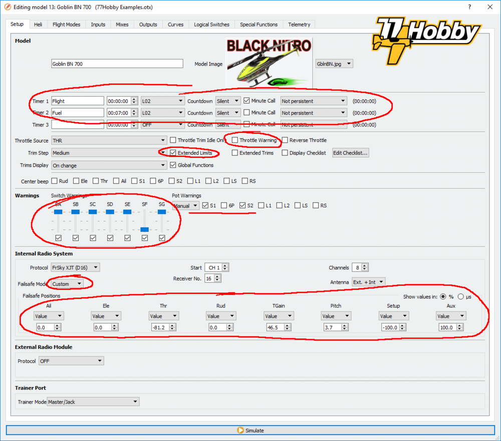
In the Setup tab, basic parameters of the model are set, such as the name, photo, binding parameters of the receiver, etc. As these are basic and self-explanatory parameters, the article focuses on the sections of timers, warnings and failsafe.
Another important parameter – which is not included in any of the sections mentioned above – is the Extended Limits parameter. To fully understand the operation of this option it is necessary to know how the rules of the Inputs, Mixes and Outputs tabs work, so I discuss the Extended Limits option only when discussing the Outputs tab. At the moment I will only write, that in my experience the Brain 2 controller requires selecting this option.
Timers
Timers count the time when its trigger switch is active. In the simplest configuration, to trigger the timer it is enough to assign any switch (e.g. Kill-Switch SF↑) and the timer will count the time as long the switch will remain active. In our example however, we want the timer to count the time from the moment when the main rotor is started for the first time (Kill-Switch SF↑ + Spool-Up SA↓), until the engine is purposely turned off by a Kill-Switch SF↓. We want the timer to operate without interruption, even if in the meantime we switch the Throttle-Hold / Spool-Up several times, e.g. to practice the auto-rotating landing.
Such functionality can not be achieved with a normal, physical switch. However, OpenTX has virtual logical switches that can be used in configuration, as good as physical switches. However, logical switches can be controlled in an advanced way using logic functions, time dependencies, triggering in the event of certain conditions, and much more.
Logical switches are named with a capital letter L and a number consisting of two digits, e.g. L07. OpenTX offers 64 logical switches.
Each logical switch can take two states:
- active / logical value: true
- not active / logical value: false
At this point, it is necessary to clarify when the OpenTX switch (each, physical or logical) will be considered active for defining rules on the Logical Switches screen.
The physical switch will be considered active when it remains in the specified (expected) position. In example SF switched to its ↑ position.
The logical switch will be active when conditions defined by rules are defined in the Logical Switches tab, e.g. when two physical switches are in certain positions at the same time, when the voltage value will be below 7.4V for more than 3 seconds, etc.
To achieve the intended purpose of controlling the timers I use the L02 switch configured in the Logical Switches tab as follows:
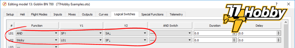
Definition of the logical switch L02 begins with the definition of a simpler switch L01, which will be active (logically true) if simultaneously two physical switches will be active (Kill-Switch and Spool-Up, SF↑ and SA↓ respectively). However, we can not use L01 directly to control the timer, as the L01 will stop being active every time you activate the Throttle-Hold function (because the SA switch will stop being in position ↓). With each activation of Throttle-Hold the timers would stop.
Therefore, in the second line I define the logical switch L02, using the Sticky function. This function works in such a way that it activates the switch when the first parameter is activated (column V1), then leaves the switch active (“sticky”) until the second condition defined in column V2 becomes true.
In our example, we have the following definition of L02:
L02 Sticky L01 SF↓
In this case, the Sticky function causes the L02 switch to become active after activating the L01 switch. Then – regardless of the state of L01, so we can switch Throttle-Hold / Spool-Up many times – L02 remains active, until the switch SF↓ becomes active. In other words, until we will switch the engine off with the Kill-Switch.
With understanding how the L02 switch works, we can go back to the timers.
We define two timers:
- Flight – counting from 00:00:00 (with this definition the timer will be counting up), giving a minute message of elapsed time (“Minute call” option).
- Fuel – counting from 00:07:00 (that is 7 minutes; when defining any value the counter will automatically count down). After the time has elapsed, the timer will trigger an automatic voice message notifying you that the time has elapsed.
Both counters are defined as “Non persistent”, meaning their value will not be permanently saved and will be reset for each flight.
The values saved permanently (“Persistent: manual reset”) can be useful, for example, to measure the total time that the model spent in the air. Their values will be saved in the radio’s memory, until they are manually and purposefully reset.
Both timers become active (they start counting) all the time when the L02 switch remains active.
As you can see, the entire logic of our assumed functionality was actually implemented in two lines of the L01 and L02 logical switches definition. Logical switches are a powerful OpenTX tool that offers virtually infinite configuration options.
Warnings
In the warnings section, we define the default position of the switches and potentiometers. When starting the radio, when changing the model and during a flight reset, the preset positions will be cross-checked with the actual positions of the radio switches and a warning will be trigger if they are not aligned.
If the switches are not in the desired positions OpenTX will display a warning that will be closed after switching all switches to the expected positions or deliberately ignoring the warning. This mechanism is intended to increase the safety of model use, by avoiding accidental activation of the function, in particular accidental engine start. This is not as important for internal combustion engines (as they will not start without a starter anyways), but it is of prime importance for models with electric motors.
In our example, we want all switches to be in the ↑ position of each other, that is, inactive by default. The exception is SF, whose default position is SF↓, for reasons that I described earlier.
We also check the position of the two potentiometers: S1 should be in the maximum position (make sure that the voice messages will be heard), and S2 in the middle position (corresponding to the middle range “tail gain”). I do not know how to set specific positions of the potentiometer in OpenTX Companion, but in OpenTX on the radio you can set a specific position of the potentiometer by setting up its desired position and long pressing the ENTER button (all that when editing the warning setting for a given potentiometer).
Of course, from the point of view of OpenTX, nothing happens if the switches or potentiometers are in different positions and we will ignore the warning. It is important, however, that we should be aware of what functions are active or in what state they are when the model configuration is started in OpenTX.
There is one more option regarding warnings in the Model section of the Setup tab. It’s about Throttle warning. For most models, this option should be marked, because at the time of starting the model, for safety reasons, the throttle should be closed. However, in the case of the helicopter configuration, the position of the Throttle stick does not have the slightest significance, as the CH3 gas channel is not controlled by the stick. Therefore, the Throttle warning option is unchecked, and OpenTX will not warn you about the position of the Throttle stick.
Failsafe
In the failsafe section, set the positions of all eight channels that the receiver will set in case it loses connection with the transmitter.
Note: This is for specific channel values, from -100% to 100%.
The Ailerons (CH1), Elevator (CH2), Rudder / Tail (CH4) channels are set to zero, which is the neutral position of the corresponding sticks.
The Throttle (CH3) channel is set to the value corresponding to the Throttle-Hold position. Thanks to this model rotors will not be driven, but if the connection is recovered, the model will be fully controllable.
The TGain (CH5) channel is set to the value that we normally use in flight, usually the middle value of the S2 potentiometer.
The Pitch (CH6) channel is set to a value corresponding to an angle of 0° (or slightly positive) of the main rotor blade pitch. The idea is that the model should descent, but with rotating blades, producing at least a minimum lift (kind of auto-rotation, but with no negative pitch to avoid adding rotational speed to the blades).
The Setup (CH7) channel is set to the first flight mode.
The Aux channel (CH8) has probably the most important task. In the Brain 2 controller, he is responsible for activating the “Rescue” function, the emergency self-leveling of the model. In case of a failsafe situation (i.e. loss of RC connection), the appropriate setting of this channel activates the “Rescue” function of the Brain 2 controller and will maintain it until the RC connection is recovered or the power is turned off. As a result, the model is leveled, it will climb for a given time (if “Rescue” in Brain 2 has been configured this is 0.6 sec by default), then Brain 2 will try to maintain the horizontal position of the model during descent (the “Rescue” function remains active). In combination with the disengaged motor, almost neutral angle of the blades and the neutral position of the sticks, we have a chance to:
- Recover the RC connection, and with it control the model and the ability to perform auto-rotation or even – if the engine was not turned off – continue the normal flight (of course, it was recommended to land as soon as possible and check the cause of temporary loss of control)
- that the model will fall down smoothly and horizontally, in the worst case minimizing possible losses
OpenTX Companion – Heli tab
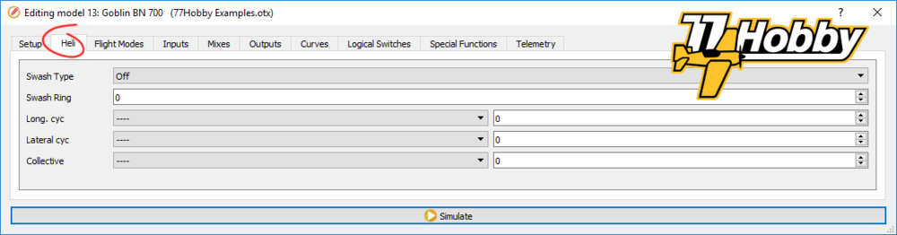
This tab is useful only if it is the OpenTX to be responsible for mixing the servos of the main helicopter rotor (cyclic), which is the case usually for flybar helicopters. When using flybarless controllers, the options from this tab are not used (all the channels are transferred directly to FBL controllers, including Ailerons, Elevator, Throttle and Rudder sticks). It is the flybarless controller unit which is responsible for their proper mixing.
The Heli tab may be even inactive at all (invisible). It depends on whether it was selected when compiling and loading OpenTX.
OpenTX Companion – Flight Modes tab
The flight modes allow you to define various configuration sets, which can then be activated by a switch. Depending on the currently selected flight mode, you can also perform various other activities, e.g. activate specific rules in the channel mixer.
The given flight mode can be activated immediately after switching or can be activated as a fluent transformation from one flight mode to another, according to the Fade In and Fade Out parameters.
OpenTX allows you to define up to nine flight modes, numbered from 0 to 8. In the following paragraphs I will often describe them as FM0, FM1, FM2, etc. FM0 is activated by default when starting the model in OpenTX. FM1-FM8 must be activated using the switch.
Three flight modes will be used to implement the project’s objectives:
- Flight Mode 0 (Normal)
- Flight Mode 1 (Sport)
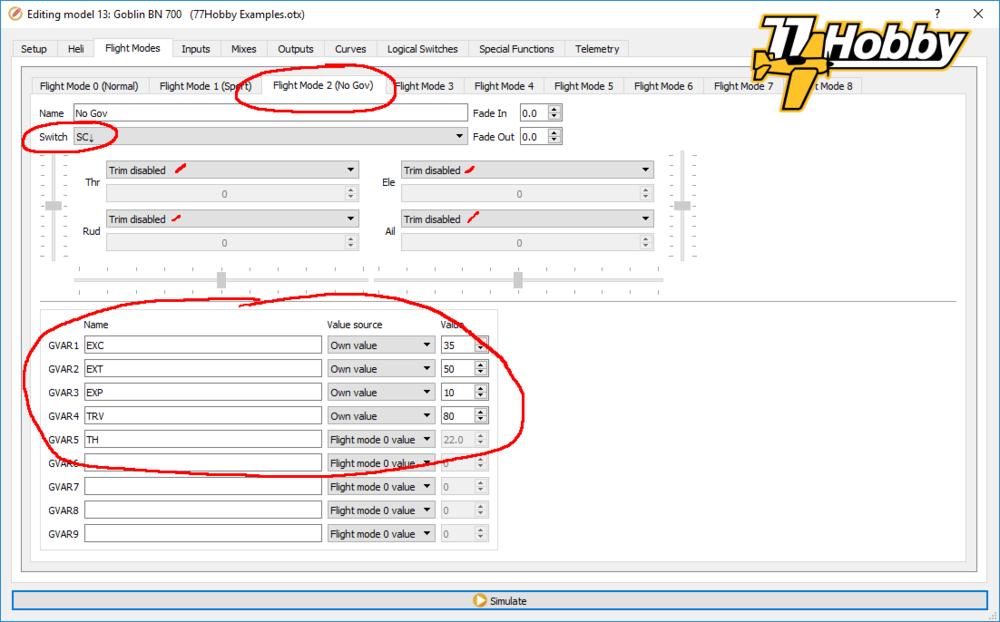
- Flight Mode 2 (No Gov)
In the flight mode tab, among other things, the name of the flight mode can be defined. The name of the active flight mode is displayed on the RC radio screen.
For flybarless helicopters, sticks trims are not practical. Therefore, to avoid accidental use, trims will be disabled for all three modes.
One of the most interesting functionalities of flight modes are global variables, whose values are used in other places of the OpenTX configuration.
Each flight mode offers 9 independent variables, numbered from 1 to 9, which can also be given three-letter names.
Global variables are used to define values that are used repeatedly in various configuration locations. For example, the expo value can be assigned directly in the mixer as a specific value, for each channel separately (suppose it is the same expo for ailerons, elevator and rudder). However, if we wanted to change the expo value, which was configured that way, we would have to edit lines of the mixer configuration separately. When a global variable is used instead (i.e. as a parameter of mixer rules), change need to be implemented in one place only. What’s more, you can assign a potentiometer as a value source of a global variable and smoothly change the expo value as you fly, for all channels at once.
Another use of global variables is to determine the values that we then want to dynamically change without having to enter the OpenTX configuration menu. Global variables can be changed by switching flight modes or by using special functions, i.e. by assigning a switch that increases, decreases or overwrites the value of a given variable.
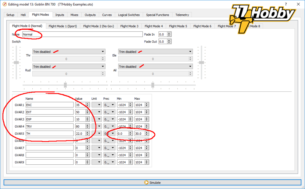
In our project we define the following global variables:
- GVAR1 – EXC (abbreviation for expo cyclic, for Ailerons and Elevator channels)
- GVAR2 – EXT (short for expo tail, for Rudder channel)
- VAR3 – EXP (short for expo pitch, for Pitch channel)
- GVAR4 – TRV (short for travel, setting max throw of a channel)
- GVAR5 – TH (abbreviation for Throttle-Hold, value for throttle channel to idle the motor)
Each global variable stores a numeric value.
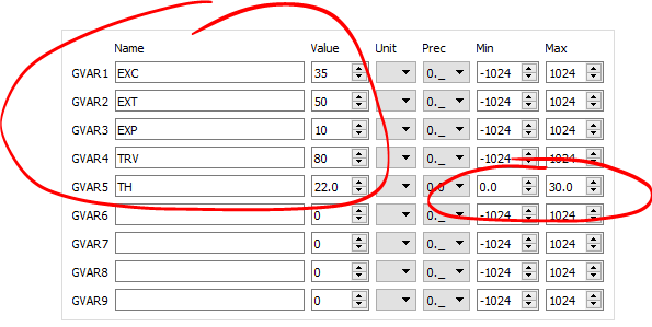
The actual expo values are of course dependent on your personal preferences. In our example (for FM0 flight mode) it is 35 for Cyclic, 50 for Tail, and 10 for Pitch.
The value of TRV variable for the flight mode no. 0 (FM0) is defined as 80. This variable will be used later in the definition of inputs to limit the travel of Cyclic and Tail for FM0. Thanks to this, in this flight mode the model will be slightly less sensitive to the sticks movement, which can be helpful for novice pilots.
The value of the TH variable will determine the value of the Throttle channel for engine idling (so-called Throttle-Hold) and has been selected experimentally. Due to its nature (idle throttle position should always be the same, at least in a given flight) this value will be the same for each flight mode. Additionally, for the TH variable there are defined limitations of the minimum and maximum values, respectively 0 and 30. Thus, the variable TH will not be able to accept negative values (protect Throttle servo) or greater than 30 (do not allow too high idle speed).
Note: Unfortunately, in the current version of OpenTX (2.2.3) there is an error that does not allow you to define a negative increment value if the defined minimum value of this variable is zero. Therefore – until this error is corrected – it is necessary to define here a negative value by which we intend to decrease the TH value in the special functions tab (in our example -0.5, defined in rule SF30 in the special functions tab). This error has already been reported to OpenTX programmers, so it is possible that in the current version of OpenTX this problem no longer occurs and you can define value of zero here. It is easy to check if the error has been corrected by entering zero as the minimum value, and then try entering a negative value in rule SF30 in the special functions tab. If it can not be done, this error still exists and you must define -0.5 as the minimum value.
The value of the TH variable will be changed using the Throttle trim switch, but in a special way, not using the standard stick trimming mechanisms of the OpenTX. Thus – in all flight modes – stick trims are disables. This does not mean, however, that we can not use trim switches, in the same way as any other switch in OpenTX. I will describe this in detail later in this article.
In flight mode 0 only numeric values can be assigned. There is also possible to define units, accuracy (integer values ”0._”, or to decimal parts “0.0”) as well as minimum and maximum range. All this separately for each variable:
For flight modes 1-8, variables may have separate values per flight mode, or they may take values defined in for other flight modes. In the example below in flight mode 1, the variable TH has a value that we have defined in the default flight mode (FM0). The remaining variables have their values, other than in the remaining flight modes:
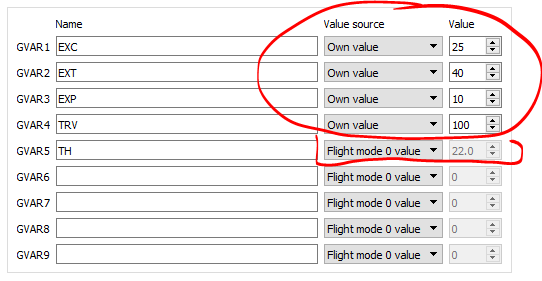
If the variable values are changed during use (e.g. setting the level of idle level), they will be remembered between radio power on/off cycles, and their last values will be read when the radio is switched back on.
Flight modes, other than the default FM0, are activated using the switch. In our example SC- for FM1:

and SC↓ for FM2:
As you can see on the screens above, we define the slightly more sensitive EXC, EXT and EXP values in the Sport flight mode. We also set the full range (100 instead of 80) for the TRV variable, which will translate into the way the Cyclic and Tail channels will work.
In the No Gov flight mode, we use the same expo and range values as for FM0, although explicitly defined as numerical values.
Summing up, by activating particular flight modes, we can change the values stored in global variables. These variables can then be used in various configuration locations instead of giving specific values. This allows you to change the value in one place, but the effect of this change will be visible wherever the variable has been used. The defined variables can also be changed dynamically, using special functions (without having the necessity to alter it via the configuration menu).
We will use global variables in the next OpenTX Companion configuration tab.
OpenTX Companion – Inputs tab
The OpenTX philosophy is based on the processing of input signals that cause specific actions at the system outputs. Simply saying, OpenTX reads the input values (i.e. position of the control stick), then performs actions according to the configuration set (flight modes, inputs, mixer, logic switches, special functions, telemetry) so that at the end of the process the desired state of output channels is achieved.
The outputs in OpenTX are channels sent as control signals to the RC receiver. OpenTX can drive up to 32 channels. For example, the FrSky protocol ACCST limits this number to 16 for one sending module (which is still quite a lot of channels). If it was necessary to use more than 16 channels, you can use two transmitting modules (i.e. an internal XJT module built into each Taranis or Horus, plus an external XJT transmitter module, mounted in the expansion slot on the back of the housing – 32 channels total).
In OpenTX world an input can be practically everything, of course within the components available in the system:
- control sticks
- trims
- physical switches (usually two or three positioners)
- potentiometers (rotary or slide, adjustable smoothly or 6-position)
- logic switches
- outputs (values of output channels)
- other entries
- telemetry parameters (i.e. RSSI, commonly used to send the value of the received RC signal strength, back to the receiver, as one of the channels, for use by flight controllers in the model)
- cyclic parameters (if the heli tab is active)
- LUA script outputs (programming language for writing simple programs that can be run in OpenTX)
- special value “MAX”
Each input defined becomes a parameter that can then be used in other places of the OpenTX configuration. In particular in the mixer, which I will describe in the next section of the article.
OpenTX inputs are marked with a capital letter I (from Input) and a number, i.e. I3. OpenTX supports up to 32 inputs.
In the Inputs tab, we define rules (one line is one rule) assigned to a given input. You can assign multiple rules to one input, but in the example configuration I do not use this option, staying with one rule per entry:
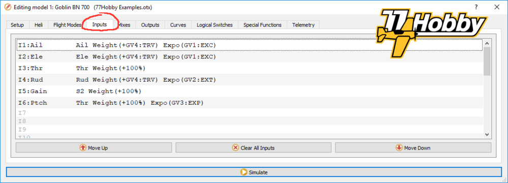
Therefore, we define six input rules, which we give names (max. four letters):
- I1 (Ail) – the source for this input is the physical stick Ailerons or – being more specific – the value from -100% to +100% related in proportion to the movement in the horizontal axis of the right control stick (assuming that the radio works in MODE 2). I use the term “physical stick” here. This will be important later, when I discuss the differences between the defined input and the physical “source” of this associated input.
- I2 (Ele) – the Elevator’s physical stick.
- I3 (Thr) – physical Throttle stick.
- I4 (Rud) – physical Rudder stick.
- I5 (Gain) – physical rotary potentiometer S2, which we will use to dynamically (i.e. during the flight) adjust the gain P for the tail rotor.
- I6 (Ptch) – the source for this input is the Throttle stick (the same as for the I3 input). However, input I6 will be used to adjust the pitch of the rotor blades of the main helicopter, which is why we define them as a completely separate, independent input (as i.e. we will be changing the pitch, but not changing the throttle in the same time).
Each line of the Inputs tab contains a rule assigned to a given input, saved in abbreviated form. For the I4 rule, this is:
I4: Rud Rud Weight (+GV4:TRV) Expo (GV2:EXT)
After double-clicking the line of this rule, a dialog box opens, in which you can set detailed parameters of a given rule:

The name of the input is then used in the mixer, instead of or next to the input identifiers (i.e. instead of I4 we have Rud).
The name of the line is displayed next to the given line in the Inputs tab. It can be useful as a note or comment, especially when we have more rules assigned to one entry and we want to somehow mark for the future what the de-facto rule does.
Source defines where the input should get the value. In the above example, the source is the Rudder stick. With Include Trim option you can choose whether to take into account the corresponding trim for a given source.
Weight defines the percentage, on a scale from -100% to 100%, what part of the value of the source is to be assigned to a given input, i.e.:
- the weight of 100 means that the value of the source will be assigned to 1: 1, i.e. the stick in the 50% position will give the same 50% on the input.
- weight -100 means that the value of the source will be kept, but with the inverted sign, i.e. the stick in the 50% position will give -50% on input
- the weight of 70 means that the value of the source will be multiplied by 0.7 (70%), i.e. the stick in the 50% position will give a 35% output.
- weight -30 means that the value of the source will be multiplied by -0.3 (-30%), i.e. the stick in the 50% position will give -15% output
- etc.
The weight can be defined as a numerical value, but it can also be a global variable (GV). In the example above, we use the variable GV4 (TRV). In that way, the value of the input range Rud (I4) is changing as the current value of the variable TRV changes. As we remember from the previous part of the article, this variable changes its value along with the choice of the flight mode (takes on the value of 80 or 100). Thanks to the fact that we use the same variable as a weight of the range for the Ail and Ele inputs as well, effectively we get a variable (but the same) working range for cyclic and tail rotor, switching with flight modes change. At the same time, the configuration of inputs remains very simple and clear, without a large number of rules.
Next in the configuration dialog box we have an offset, which we do not use. In short, the offset adds a numerical value (or value stored in the global variable) to the source value, i.e. if the source value is 30%, then after adding the offset 20, the entry value will be 50%.
Then, to the definition of input Rud the Expo type curve is assigned, with the value stored in the variable EXT. Assignment of the global variable works the same as in the case of the previously described weight: the expo value will change with changes in the global variable value GV2 (EXT), which in our example follows with changes in the flight modes.
In the Flight modes section, we define in which flight modes the rule (line in the Inputs tab) is to be active. In this case, we indicate that this rule is to be active in all nine flight modes (numbered 0-8).
You can see here how useful and powerful global variables are. Without them, in our example we would need to define three rules for each of the inputs (Ail, Ele, Rud) to achieve the required functionalities (i.e. ranges and expo variables with flight modes), assign them particular weight and expo values, and then mark in which flight modes the rules should be active. Thanks to the use of variables, we have only one rule per Inputs tab entry, while the weight and expo are changed in the background, by altering the global variables.
There are two other options in the Rud’s rule definition dialog which we do not use: Stick and Switch Side. Each rule can be rendered active only when the system is assigned to the switch, wherein the definition of the switch is quite wide, it is not only the physical radio switches). You can also assign the effect of the rule only to the positive or negative part of the Stick Side axis, i.e. the rule for the Throttle stick will be active, but only above 0% (that is, from the middle position up).
The Inputs tab is a good place to define expo values and ranges of control sticks. It is also good practice to define other important inputs here. In our example, this is the I5 rule, whose source is the potentiometer S2 used to adjust the gain P for the tail rotor PID controller; and also the rule I6, which will serve as an input to control the overall pitch of the main rotor blades.
Thanks to such definition of the inputs, we will simplify the rules in the mixer tab significantly, and the entire OpenTX configuration will be very transparent, with clearly separated function blocks.
OpenTX Companion – Mixes tab
Closed operating systems of RC radios of traditional modeling companies are usually based on pre-defined model configuration templates, in which various options are then selected, adapting the functionality of the selected configuration template to the requirements of a specific model. However, everything is done as part of the templates and options provided by the manufacturer of the radio. Often the order of channels in the receiver is pre-defined, and the servos must be connected to appropriately marked receiver ports (i.e. Ail, Ele, Thr, Rud, Aux, Gear, etc.).
OpenTX works differently. There are no templates at all, and the logic of configuring the model starts with defining what we want to achieve at the outputs (ports) of the RC receiver.
How does the OpenTX mixer work?
Mixer is the “heart” of OpenTX. Planning the configuration of the model in OpenTX starts from the mixer, specifically from determining how the output channels (ports) of the receiver should behave, i.e.:
- the CH4 channel value is to be proportional to the movement of the rudder stick
- the value of the CH2 channel is to be proportional to the movement of the elevator stick
- the CH8 channel value is to be set to 0% when the SA switch is in the middle position; and a value of 100% when the SA switch is in any other position
- CH16 channel value is to be proportional to the RSSI telemetry parameter (-100% for 0% RSSI and +100% when RSSI is 100%).
- etc.
(the above examples are only demonstrations and have no relation to the assumptions of the project that we implement)
Simplifying a bit, the output channels are nothing but the receiver ports to which the servos are connected or which is connected to the flight controller. Modern receivers can also send channel values through a special port – CPPM or SBUS – and send them with one cable to a flybarless controller. This largely limits the number of cables between the receiver and the flight controller.
More information about different types of ports used in RC modeling is described in the article RC Ports, not only FrSky .
Normally, the value of each output channel in OpenTX can range from -100% to +100%. This means that for example the aileron stick set to the left completely determines the channel value at -100%, the stick at the neutrum is 0%, and the stick tilted fully to the right is +100%.
Additional information: In fact, the value of each channel is represented by the duration of the impulse (the so-called PWM modulation). The duration of the impulse in RC models is usually in the range from 1000μs (-100%) to 2000μs (+100%), from the neutrum per 1500μs (0%). Different manufacturers, however, apply slightly different limit values (i.e. the range 988-2012μs, or the neutrum in 1520μs, more information on this subject can be found in the already quoted article RC Ports, not only FrSky ). For this reason, it is sometimes necessary to set the channel output values to more than +100% or less than -100%. In order for OpenTX to allow the use of an extended range of values, the Extended Limits option must be selected in the Setup tab, which extends the available range to ±150%.
In the Mixer tab (but also in the Inputs tab) rules are defined in lines (each line is one rule), determining how the output channels will behave. Rules assigned to a given channel (one or more rules) define what parameters affect the mixer output value for a given channel. These can be very simple rules (i.e. 1:1 mapping of the control stick) or complicated, with different weights, offsets, curves, active only in specific flight modes, etc. I will discuss most of possible configuration parameters below.
You can assign more than one rule to one channel. Each rule can be active or inactive at any given time, depending on the state of one of the switches (physical or logical) and / or depending on the currently selected flight mode.
If more than one rule is currently active for a given channel, then rules are evaluated, line by line, from top to bottom in the list of mixers. The effect of successively active rules can be added to each other, multiplied or overwritten. Initially, it may sound a bit complicated, but the rules are really simple and you only need to know and understand them in order to successfully apply them in practice. I will try to explain this on examples.
OpenTX supports up to 32 output channels numbered from CH1 to CH32.
Brief description of the mixer rule parameters
This is the Mixes tab, with the rules that implement the assumptions of our project:

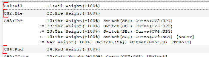
In the OpenTX mixer, each line is a rule assigned to the output channel. One rule can be assigned to one channel, e.g. as for CH1 channel:
CH1:Ail I1:Ail Weight (+100%)
but you can also assign multiple rules to one channel, i.e. two rules are assigned to CH6:
CH6:Ptch      I6:Ptch Weight (+100%) Flight mode (FM0:Normal) Curve (CV5:PT1)
	   := I6:Ptch Weight (+100%) Flight mode (FM1:Sport, FM2:No Gov) Curve (CV6:PT2)
The output value of each channel is determined based on the rules assigned to the channel which are currently active. The rules can be activated by physical switches or flight modes.
Let’s take a closer look at the two channels we have just used as an example above.
CH1:Ail I1:Ail Weight (+100%)
which after double-clicking the rule is expanded as a dialog box:
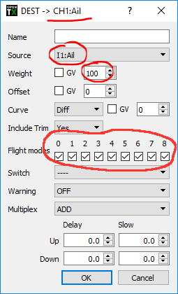
The input I1(Ail) is assigned to the CH1 channel, which in other words is the the aileron stick. The assigned weight is 100% (the scales work as in the previous example, when I described the Inputs tab). The rule has no assigned switch, but it has assigned flight modes and is active in all nine modes (FM0-FM8).
As the weight is 100%, the movement of the aileron stick is 1:1 mapped to the channel value. As a result, we’ll get -100% for the max left stick tilt, 0% for the neutral position of the stick and +100% when the stick will be tilted completely to the right. Of course, the channel value will take all intermediate values between -100% and +100%, in proportion to the position of the stick, but taking into account the expo and ranges defined for input I1 in the Inputs tab (thanks to this we do not need to specify expo values or ranges here, which simplifies the mixer configuration, makes it more transparent and easier to read later).
CH6:Ptch I6:Ptch Weight (+100%) Flight mode (FM0:Normal) Curve (CV5:PT1)
:= I6:Ptch Weight (+100%) Flight mode (FM1:Sport, FM2:No Gov) Curve (CV6:PT2)
after double-clicking on each line opens the following dialogs:
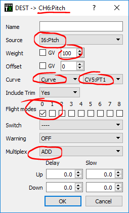
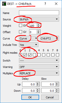
Both rules assigned to the CH6 channel defines I6(Ptch) as an input, the value of which will be taken into account when determining the CH6 output value.
As we remember from the previous section (Inputs tab), input I6 (Ptch) depends on the movement of the Throttle stick, which for RC helicopters mainly controls (sometimes even only) the pitch of the main rotor blades, not the gas throttle. Both rules use 100% weight, so the Throttle stick will be 1:1 mapped to the CH6 channel value – resulting in 0° pitch for the stick in the neutrum, -12° pitch for the stick in the lower position, and +12° pitch for the upper position of the stick. An example of ±12° has nothing to do with OpenTX. The limiting values of the blade pitch are set in Brain 2, while setting the working ranges of the helicopter rotor head. The role of OpenTX here is only the appropriate steering of the FBL controller.
This time, additional conditions are defined for CH6 rules:
- the first rule is active only for flight mode no. 0 (FM0, called Flight Modes)
- the second rule is active for FM1 and FM2
Controlling which rule is active takes place outside the mixer by selecting particular flight mode.
Both rules have assigned curves:
- to the first rule, curve CV5 (curve No. 5, named PT1), limiting the pitch range of the main rotor blades to 85% (to approximately ±10°).
- to the rule of the second curve CV6 (PT2), giving the full pitch range ±12°
I will discuss the curves later in the article. At this point, it is only important that by such configuration we assign two different curves to the same output channel, depending on the chosen flight mode.
The effect of this rule mixing for CH6 can be seen in the radio simulator:
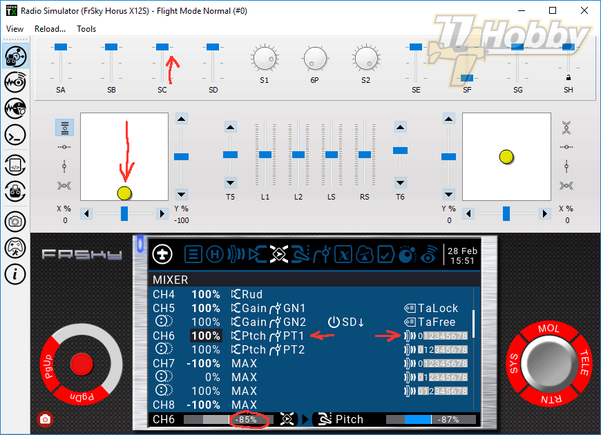
This is not perfectly visible on the above screenshot, but currently active rules are marked with bold font in the second column (on the screenshot active rules are CH4, CH5, the first CH6 rule, the first CH7 rule, and CH8). There are other active rules, but these are outside of the view).
In our case, because the active mode is the default FM0 (SC switch in position ↑), only the first rule is active for CH6. This rule applies a curve to the channel that limits the CH6 channel range to ±85%. Thus, despite the fact that the throttle stick is fully down, the channel value at the mixer output is -85% (and not -100% as it normally would for the Throttle in fully down position). The actual output value of the channel is -87% and this is due to the physical ranges of the output values of the channels defined in the Outputs tab (I will discuss this when describing the Outputs tab).
Since the flight modes activating the rules do not overlap (individual rules for the same channel are activated by other flight mode), there are no complications caused by several rules active for the same channel at the same time (I will discuss such a situation later, when discussing the rules for the CH3 channel).
Inputs I1-I32 vs. direct reading of physical manipulators
As a source of a mixer rule we can choose various parameters available in OpenTX. These can be physical positions of radio manipulators (sticks, trimmers, potentiometers, switches), logic switches, telemetry parameters, values of other channels, etc. OpenTX is very flexible here, virtually any parameter – physical or virtual – can be used as a source.
Particularly important sources are Inputs, marked in OpenTX as I1-I32. These are the same inputs that we configured in the Inputs tab.
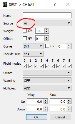
In the above examples, we used previously defined inputs, i.e. I1 entry named Ail:
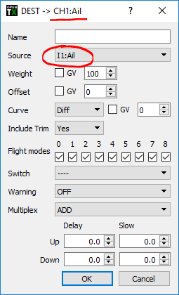
The definition of the same rule would look very similar, but using Ailerons (ailerons) directly as a source:
(note the lack of “I1:” in the source definition)
It may seem that it does not matter if you use the previously defined I1(Ail) input or Ail stick directly. Actually, it is just the opposite.
First of all, if we defined the inputs in the Inputs tab, we probably wanted to use them in the mixer. Otherwise, the parameters defined there (i.e. expo, ranges) will never be taken into account, because in the mixer we would read the “raw” values of the source (in this case “raw” Aileron stick).
Secondly, the use of predefined inputs significantly simplifies mixer rules, which are easier to create and then read (especially after some time). A good practice is the functional separation of the areas where the model is configured. The main role of the mixer is mixing the channels, so let’t configure somwehere else whatever is not related to pure mixing (like Input expo).
Thirdly, in complicated configurations, using both input rules and mixer rules gives us increased possibilities. For example, you can assign an expo curve at the input and then – additionally, depending on other parameters – another curve in the mixer.
Fourthly, using the Inputs tab gives you the opportunity to create virtual inputs, such as CH6 (Ptch) from our example. This increases the configuration options as well as the clarity of the mixer rules.
The MAX parameter
The MAX parameter is a special parameter that always has a logical value of 1 or 100%, depending on the context of use.
The MAX parameter is used when we want to set a value regardless of the position of switches or other variable input (variable in the sense of those that can change its values; not to be confused with the Global Variables).
Let’s look at the rule for the CH8 channel from our project:
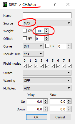
We use the MAX variable as the source here, and then apply the weight -100%. By performing a simple MAX * -100% multiplication operation we get minus 100% at the CH8 output.
As a result, the AUX channel in Brain 2 remains inactive, and the Rescue function assigned to it is on standby. We will activate it in a different way, which I will describe in the Special Functions section.
Succession and rule overwriting
So far, I have described rules that were activated by various events, but were configured in such a way that it was impossible for more than one rule to be active or potentially active at the same time – speaking about single channel of course.
In our project, we do not use rules that will actually be active at the same time. Such a configuration can be described in another article, i.e. when configuring the mixer for an airplane, in which the rudder slightly tilts also when operating the aileron shaft (i.e. 15% deflection of the aileron stick is assigned to the rudder channel to improve the driving of the model in turns) ).
In the below example, we use rules that would be active at the same time, if not for succession and overriding rules.
Let’s start by looking at this simulator screen:
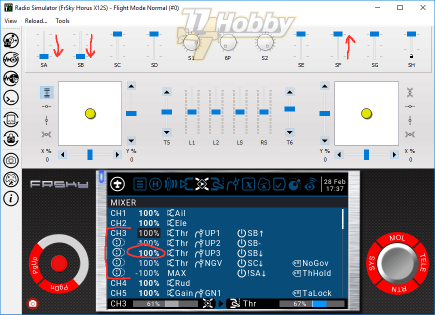
SF↑ – the engine is “armed”
SA↓ – Spool-Up, meaning Throttle-Hold is not active
SB↓ – choose Idle-Up 3, the third rotational speed of the main rotor, as defined in the governor of Brain 2
The above screen shows that the third rule for the CH3 channel is activated by the SB switch ↓. The model motor therefore rotates at the speed set as Idle-Up 3 in the Brain 2 governor.
But what happens when we move the SA switch to SA- or SA↑, or Throttle-Hold?
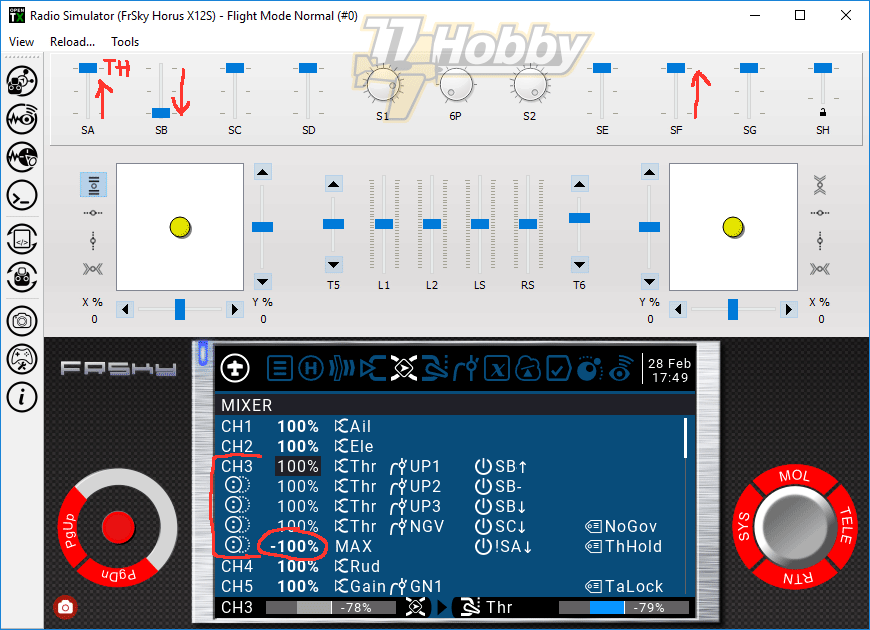
Although we have not changed the position of the SB switch (it remains in position SB ↓), the third rule of channel CH3 is no longer active. The last (fifth) rule for the CH3 channel has been activated, which happens when the SA switch is in the Throttle-Hold position (position not towards you, which is written as !SA↓ – exclamation mark means logical negation).
Two things are needed to understand what is happening:
- The rules assigned to a given channel are processed sequentially, as they are displayed in the Mixes tab list, from top to bottom.
- Each successively processed rule changes the final result, adding, multiplying or replacing the value resulting from the processing of the preceding rules.
Whether a given rule adds, multiplies or replaces the current value depends on the setting of the Multiplex parameter set in the dialog box of a given rule:
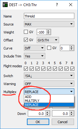
In the list of rules of the mixer tab the conversion operation (REPLACE) is marked with a colon and equal signs:

For the first rule of each channel, it does not matter which operation is set as Multiplex, because there are no rules preceding it, so there is nothing to add, multiply or replace. In particular, it does not matter when the rule is the only one assigned to the channel. Therefore, in the list of mixer rules, for the first rules of each channel, OpenTX Companion does not even show which operation is selected.
Returning to the main thread…
In our example, the last CH3 rule replaces previous values. Therefore, even though we have an active SB↓ switch (Idle-Up 3, maximum revolutions of the main rotor), in fact the final value of the channel in the mixer determined by the last rule, which is Throttle-Hold, activated by switch position !SA↓ (not towards you). As a result, the nitro engine will safely idle.
Analysis of mixer rules
We have now almost complete knowledge to analyze all the mixer rules that implement the assumptions of our project. The exception are curves, which I will describe in detail later in the article. In this part of the article, I will therefore limit myself to indicating that the curve is active and I will briefly describe the effect on the output of the channel.
Let’s recall how the Mixes tab looks like (mixer rules implementing the assumptions of our project):
We define eight channels (CH1-CH8) in the order in which they are expected by the Brain controller. The expected order of Brain 2 channels can be previewed (and even modified) in the Advanced Menu / Receiver of the Brain 2 configurator:
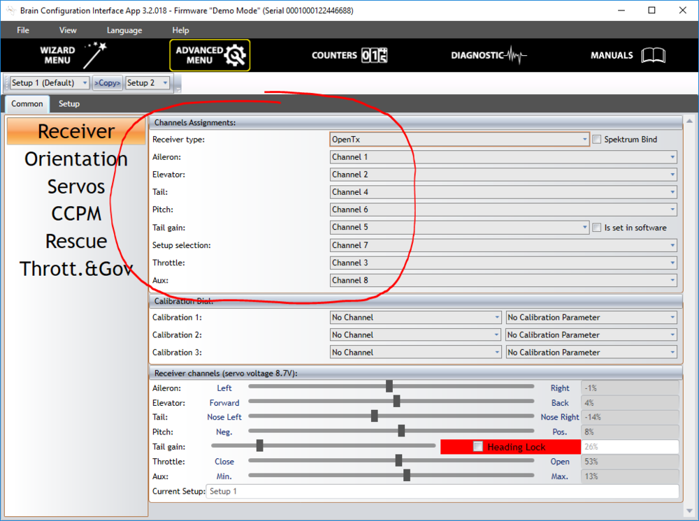
Since the order of the channels for OpenTX does not matter, we will adapt to the standard order expected by Brain 2.
Rules for CH1, CH2, CH4 channels (Ail, Ele, Rud)
These are standard channels for handling ailerons, elevator and rudder (Ail, Ele and Rud respectively):
In the helicopter, ailerons and rudder are responsible for controlling the tilting of the main rotor head (cyclic), so de-facto for rolling and pitching of the entire model. The rudder is responsible for yaw, which is accomplished in helicopters by changing the pitch of the tail rotor blades.
There is nothing special going on in the mixer rules for CH1, CH2 and CH4 channels. Each of the above mentioned channels assumes the values assigned to each other and previously defined in the Inputs tab, i.e. the aileron stick (I1:Ail), the elevator stick (I2:Ele) and the rudder stick (I4:Rud). We remember that we use the inputs defined earlier in the Inputs tab, not directly the values read from the physical sticks. Therefore, the expo and the travel range of these inputs are taken into account (determined using global variables, which are depending on the currently selected flight mode).
CH3 channel rules (Thr)
The CH3 channel controls the throttle.
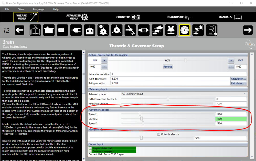
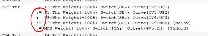
The first three rules assign to CH3 one of three curves CV2, CV3 or CV4 (with names UP1, UP2 or UP3 respectively) depending on the position of the SB switch. In this way, we implement one of the assumptions of the project, so assigning three Idle-Up speeds to the SB switch:
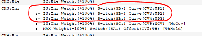
The curves activated by the SB switch cause the CH3 channel value to take one of the three Brain 2 controller governor control values, setting the rotational speed of the main rotor at certain levels:
It is worth noting that the second and third CH3 rule (fourth and fifth too) have the REPLACE attribute. As a result, if any of these rules is active, only this one rule is taken into account when determining the output value CH3 (its operation completely overwrites the previous value):
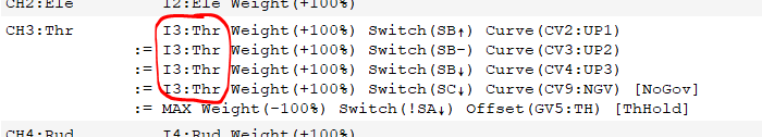
Another assumption of the project was that the SC switch in the down position turns off the governor and turns on the engine speed control in the traditional way, using a gas curve. The second part of this assumption (control of rotations using the NGV curve) is carried out by the next (fourth) CH3 channel rule:

For convenience, we have called this rule in accordance with the function performed, i.e. “NoGov”. The name of the rule, if it is defined, is visible at the end of the line, in square brackets. The name does not have any function except to make reading of the rules easy.
If the fourth rule for CH3 becomes active (the SC switch is switched to SC↓ position), it overrides the first three rules (the REPLACE operation + rules are interpreted sequentially, in order from the first up to the last on the bottom). Thus, regardless of the state of the SB switch, if the fourth rule is active, the CH3 channel will start to follow CV9 curve called NGV (No GoVernor).
Note: The first part of the project assumption (deactivation of governor at SC↓) has already been partially completed by usage of flight modes, which will affect the CH7 channel value. The rules for the CH7 channel will be explained below.
In the first four CH3 channel rules described so far, we use input I3:Thr as source:
As we will see when discussing the curves, this is not important for the first three rules (those implementing three successive Idle-Up stages). Nevertheless, it will be important for the fourth rule (No Governor). I will discuss it in more detail in the Curves tab.
The last (fifth) rule assigned to the CH3 channel performs the Throttle-Hold function.
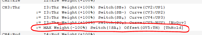
We have named this rule – ThHold – so that in the future it will be easier to read the configuration.
As the ThHold rule is the last assigned to the CH3 channel, at the moment of activation it overwrites all previous rules (it is always interpreted at the very end). Therefore, regardless of the position of the SB or SC switches, if we switch the SA to position SA↓ (Throttle-Hold), the engine will run at idle.
Note: the Throttle-Hold position of the SA switch is either its middle position SA- or its position away from you SA↑, which in short we write as “not towards you”, so !SA↓ (using the exclamation mark as already known logic NOT).
Throttle-Hold means that the engine is idling. To achieve this, we need to force CH3 to take some low value corresponding to the position of the throttle, which will ensure stable idling. As I mentioned in the discussion of the Flight Modes tab, we store the appropriate CH3 idling value (experimentally selected) in the global variable TH.
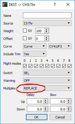
To set the value stored in the global variable TH as CH3 channel value, in the Throttle-Hold rule definition we use the special MAX value as the source and we reverse it using -100% weight. Then we apply offset (offset) by the TH value just. This is what the rule looks like when you double-click a line in the list of rules:
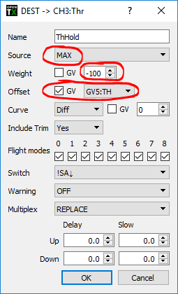
As the output value we use MAX, because it is constant and will allow us to set the Throttle-Hold value regardless of the position of the Throttle stick or the position of other switches or potentiometers.
For a better understanding, let’s write this as a kind of pattern, assuming:
- source: MAX (logical value 1 or 100%)
- weight (weight): -100%
- offset (offset): TH (that is, the value stored in the global variable TH, in our example defined as 22)
With the above assumptions, our pseudo-formula and calculations performed by the mixer will look like this:
 CH3 = MAX * WEIGHT + OFFSET
 CH3 = 1 * (-100%) + 22
 CH3 = -100% + 22
 CH3 = -78%
So in our example, -78% will be the CH3 channel value set by activating the Throttle-Hold rule.
The servo position for Throttle-Hold (or more precisely the value of the global variable TH) will then be modified using special functions (Special Functions), so be able to regulate stable idling of the engine.
CH5 channel rules (TGain)
In the Brain 2 controller, the CH5 channel controls the gain of the P component (PID controller) of the tail rotor pitch control.
Positive CH5 channel values (range from 0% to +100%) determine the gain level in the so-called Tail Lock mode – gyroscopic support of model yaw deviation. The CH5 channel’s negative values (range from 0% to -100%) determine the gain level in the so-called Tail Free mode – in which the model is subjected to aerodynamic forces and deflects (rotates in the main rotor axis) in accordance with them.
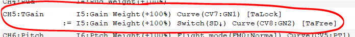
Switching modes is done using the SD switch. In the first rule – named TaLock – we do not even have to define a switch. The TaLock rule is active by default until the TaFree rule is activated, which happens after the SD switch is set to SD↓. After activation, the TaFree rule overrides the behavior of the TaLock rule. It is based on the principle of rule replacement already described before (the REPLACE option).
For both rules of the CH5 channel, the source is the previously defined input I5:Gain, so simplifying the potentiometer S2.
Normally the amplification would be regulated in the range of ±100%. In practice, the regulation should happen in a much narrower range, e.g. 40-60%. In addition, we must separate the positive and negative ranges. Therefore, curves are assigned to both rules that limit the range, and at the same time set a positive range for the TaLock rule (from +40% to +60%), and the corresponding negative range for the TaFree rule (from -40% to -60%).
Thus, in the leftmost position of potentiometer S2, the channel value is ±40%, and in the rightmost direction ±60% (plus or minus depending on the position of the SD switch). This significantly increases the resolution of the S2 potentiometer, which enables precise adjustment of the gain. Limiting values controlled by potentiometer S2 also prevents accidental setting of the extreme gain values, at which the model would behave very unstable.
By using separate curves, you can assign two different ranges if you need to: a different one for the TaLock rule and another for the TaFree rule.
If it turns out that the ranges defined by the curves are not suitable for the given model (because it is necessary to set the gain outside the range of the initially set range), change the curves so that they cover the appropriate range, i.e. ±30-50% (for a predicted gain value of 40 %).
The curves assigned to CH5 channel rules will be discussed in detail when discussing the Curves tab.
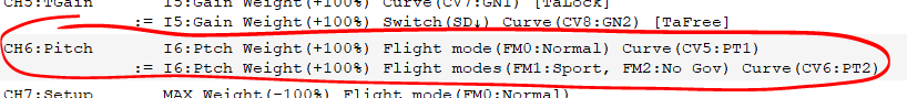
CH6 channel rules (Pitch)
The CH6 channel controls the overall pitch of the model’s main rotor blades. In the example model, the full range of the pitch is -12° / +12°, with 0° at the center position of the Throttle stick (remember that in helicopter models the throttle stick also controls (and often only) the main rotor blades), which is typical for 3D aerobatic models (allowing inverted flight).
Two rules are assigned to CH6 channel, activated by changing the active flight mode:
In both rules the source is the previously defined input I6:Ptch (throttle stick with assigned expo dependent on the global variable EXP). Movement of the stick is then pre-filtered through the input (we add a small expo, to have a slightly better control precision near the center of the stick), and then in the mixer, where various curves are assigned, depending on the currently active flight mode.
The first rule, associated with the flight mode FM0 (Normal), assigns curve CV5 (curve no. 5, named PT1) to the CH6 channel. The PT1 curve causes the negative blade pitch to be limited (it does not operate in the full range from 0° to -12°, but from 0° to about -8°).
The second rule, activated by flight modes FM1 (Sport) and FM2 (No Gov), assigns curve CV6, named PT2, to the same CH6 channel. As a result, the movement of the throttle stick will be reflected in the full movement range of the blades pitch, from -12° to 12°.
This is another example of how many things happen depending on the chosen flight mode, and at the same time, as with the thoughtful use of flight modes (and previously defined inputs), the rules of the mixer become logical, transparent and easy to read.
More about the curves PT1 and PT2 assigned to CH6 channel I will write in the further part of the article.
CH7 channel rules (Setup)
The CH7 channel controls the selection of flight mode (Flying Style) in the Brain 2 controller:
- CH7 = -100% – flight mode 1 (Setup 1)
- CH7 = 0% – flight mode 2 (Setup 2)
- CH7 = +100% – flight mode 3 (Setup 3)
Note: in fact, in Brain 2 a range of channel’s value will activate each mode (i.e. the value of 15% probably will also activate Setup 2), but for simplicity, let’s assume specific values of -100% / 0% / +100%. The same applies to other channels where certain options are selected, e.g. CH8.
In the OpenTX mixer, the Brain 2 controller flight modes are implemented using the following three rules:
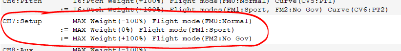
We again use the special value MAX as a fixed base value, then modified using the weight, to achive the desired output value of the CH7 channel. For example, for rule two:
CH7 = MAX * WEIGHT
CH7 = 1 * 0%
CH7 = 0%
As a result, the 0% weight assignment resets the channel values. The -100% or +100% weight would give the same -100% and +100% at the CH7 output.
Individual rules assigned to the CH7 channel are activated by usage of flight modes – each rule has a different flight mode assigned. In this way, only one rule is active at a time and its output value is sent to the FBL controller.
CH8 channel rules (Aux)
The CH8 channel activates the “rescue” function of the Brain 2 controller.
For now, however, we only configure one rule in the mixer:
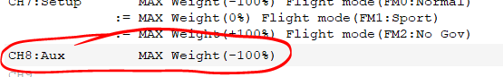
It sets the channel value to -100% and the “rescue” function remains inactive.
We will activate the “rescue” function of the Brain 2 controller outside the mixer, from the Special Functions tab, which I will write about later in the article.
OpenTX Companion – Outputs tab
The Outputs tab defines the parameters directly related to physical output devices, for example such as servos or channel outputs transmitted via the SBUS or CPPM port from the receiver to the flight controllers.
In OpenTX, signal processing from inputs (including physical sticks, switches and radio potentiometers) to outputs (channel values sent by the radio transmitting module) takes place successively in the Inputs tabs (optional), then in Mixes and finally in Outputs.
It is a good practice to start from the Inputs tab as the first configuration step, at least for the most important entries. Then the signals are processed in the Mixes tab to complete the process in the Outputs tab:
Inputs -> Mixes (Mixers) -> Outputs -> Transmitting module RC
… to complete the graphical signal processing scheme in OpenTX
When defining rules for inputs and mixers, we use the range of ±100%. These are the values used to perform calculations on the rules of inputs and mixers, assuming that the output devices are perfect and all the same.
This assumption is obviously wrong. Servomechanisms are produced by different manufacturers, they work with different resolution, they may have a slightly different center, other maximum ranges, etc. The same applies to the parameters of inputs expected and read by flight controllers / flybarless units.
Therefore, very often we will have to deal with a situation where the signal coming from the mixer, with the theoretical value of 100%, does not correspond exactly to what we would like to achieve on the output device, i.e. the servo’s horn will be a bit too big or too short.
We could adjust the values in the mixer to achieve the desired min and max positions. However, this would be a very inelegant and cumbersome solution. Imagine the output of two ailerons, for which individual center values should be adjusted and maximum swing in each direction (aileron up, aileron down). Mixer rules would become complicated. It would be necessary to use individual shifts, curves, weights for each aileron; probably create separate rules for swinging in each direction.
This approach does not make sense. In the mixer, we want the center to always be defined as 0%, and the maximum values always as ±100%.
That is why you need the Outputs tab, in which the final adjustment of the sent control signals to the physical devices that perform them is performed: i.e. servos, flight controllers / flybarless.
In our example the flybarless controller is Brain 2, which configuration of input channels (output from OpenTX) looks like this:

One of the first steps performed when configuring each flybarless controller is adjusting the ranges, in particular for control sticks and potentiometers (if the function assigned to them requires precise control). The point is that the actual range of output channel values (PWM ports or SBUS / CPPM channels of the receiver) ideally corresponds to the ranges read by the flight controller / flybarless. In other words, -100%, 0% and +100% sent by the radio transmitting module, was read by the flight controller / flybarless as the exact same value, and not i.e . as -99%, 1% and 102% respectively.
For such adjustment of the signal ranges, the Outputs tab is used:

Parameters defined in the Outputs tab will be “superimposed” on individual output channels at the very end, after the mixer rules, just before sending the processed signals by the radio transmitting module.
Actual output values are very clearly visible in the Mixes tab, when you set up the model directly on the radio (not in OpenTX Companion) or in the OpenTX Companion simulator:
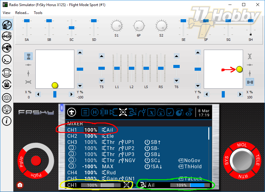
The simulator shows that the aileron stick is moved all to the right, which translates to 100% at the output of the CH1 channel mixer (marked in yellow). At the same time, the actual channel value sent by the radio transmitting module is 109% (marked in green). This is due to the fact that the maximum CH1 channel value has been adjusted to 108.6% in the Outputs tab (rounded up to save space on the screen, shown as 109%).

Once we know the basics of the Outputs tab, we can proceed to calibrate the outputs, as expected by the flybarless controller. In our example, this is Brain 2, but the same principle will apply to other flight controllers. We mainly calibrate the outputs of these channels whose operation must be precise. In our example, these are control sticks (CH1-4 and CH6):
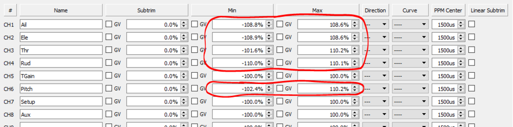
To calibrate a given channel, run the Brain 2 configuration program in the Transmitter Setup tab and carry out the following procedure for each channel:
- move the stick of the given channel to the position -100% (left or down)
- we observe the channel value read by Brain 2; it should be close to -100% (except for Throttle, where the scale is from 0% to 100%, so the expected value here is 0%)
- in OpenTX (on the radio, not in Companion) in the Outputs tab, adjust the Min value of the given channel, so that Brain 2 shows exactly -100% (or 0% for the Throttle channel)
- move the channel’s stick to the position +100% (right or up)
- we observe the channel value read by Brain 2; it should be close to +100%
- in OpenTX (on the radio, not in Companion) in the Outputs tab, adjust the Max value of the given channel, so that Brain 2 shows exactly +100%
Calibration should be carried out yet without weights or curves limiting the range, without offsets, etc. Of course, to perform the calibration it is necessary to connect the receiver, bind it, pre-set the receiver type in Brain 2, etc. Calibration should be carried out in OpenTX on the radio (not in OpenTX Companion).
After calibration, we should have output channels from the OpenTX mixer perfectly tuned with the Brain 2 controller inputs (or other flight controller). Tuned in, meaning that when the OpenTX mixer shows ±100% (on the simulator screen above highlighted in yellow), the controller should display the same ±100% (or 0% for the minimum Throttle channel position).
This basically exhausts the description of the configuration of the outputs of our sample model, but for the sake of providing complete information, I will discuss further fields that can be defined in the OpenTX Outputs tab:
Name – The name displayed in the Radio Mixes tab, in the channel monitor and in the failsafe setting.
Subtrim – A value that shifts the actual center of a given channel, to adjust the factory position of the servo’s horn to 0% of the channel’s value in the mixer. Usually, this field is not written directly, but after trimming the model on the fly, the trimming value is copied to the sub-channel of the channel, using the Copy trims to subtrim option :
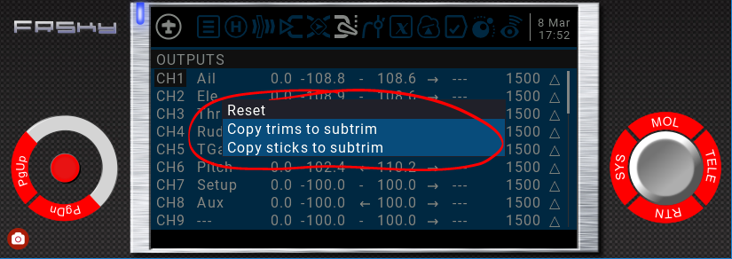
Thanks to this, the trims can be set back in zero or even turned off, and the correction will be remembered and applied by the sub-trim field of the outputs tab.
(Alternatively, you can copy to the subtrim the values corresponding to the current position of sticks Copy sticks to subtrim, which can also be done using the special function Instant Trim )
Moving the channel center with the help of a sub-channel does not cause an adequate change in the channel’s min / max values (min / max values +/- 100% remain at the same level, see the red line in the below chart).
Min / Max – correction of the actual min / max values of a given channel. This is where we enter values slightly larger or smaller than 100%, so that for the value of 100% in the mixer, reach the desired extreme position servo or the channel value sent to the flight controller / flybarless. In our example, we did it for CH1-4 and CH6 channels.
In Subtrim / Min / Max global variables can be used as well. Just select the GV option located next to each field and select the appropriate global variable.
Direction – used to reverse the direction of the servo or channel sent to the flight controller / flybarless. Thanks to this, we can use intuitive values in the mixer, i.e. 100% indicating the maximum positive deflection (i.e. stick moving to the right), when the servo is actually leaning in the opposite direction (i.e. to the left). To correct this behavior, we do not need to change the value in the mixer to -100%, which could be confusing from the point of view of the implemented action logic. Instead of changing directions in the mixer, we simply invert the operation of the servo in the Outputs tab. Of course, the same applies to the channel values sent by SBUS / CPPM links to flight controllers or flybarless units.
Curve – this is just one more place (except the Inputs and Mixes tab), in which you can assign a curve to the channel.
PPM Center – defines the center of the channel, in the notation of PWM pulse duration defining the center (i.e. in micro seconds – μs). By default, OpenTX uses 1500μs and the range 988-2012μs for channel values of -100% and +100% respectively. Changing the PPM Center option works similarly to Subtrim, with the difference that the extreme values will also be shifted accordingly. For example, by changing the PPM Center from 1500μs to 1520μs, the extreme values will also be shifted by 20μs, ie to 1009μs and 2032μs respectively. An example of using the PPM Center (moving the PPM center down) is shown by the yellow line in the graph below).
Linear Subtrim (Linear Subtrim) – affects how min / max values behave when changing Subtrim. Without the Linear Subtrim option (default is not selected), the min / max values are not changed, they remain the same. Only the location of the channel center changes, and as a result the channel works asymmetrically, but still achieves the same extreme values (red line on the graph). If the Linear Subtrim option is selected, the extreme values of the channel data will be adequately shifted and cut off on one side, and on the other hand the maximum value will be reached earlier (blue line on the chart).
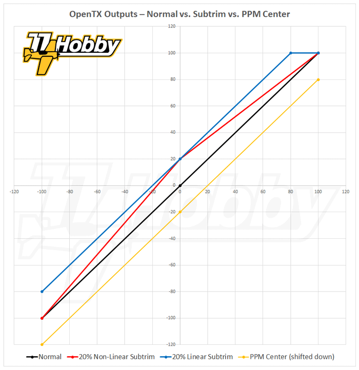
Extended Limits
At this point, it is worth mentioning the Extended Limits option which you can select in the Setup tab.
Normally OpenTX uses 1500μs on the outputs as a neutrum and 512μs on each side ±100%, effectively the range of 988-2012μs (again I refer to the article Ports not only FrSky if you don’t know what I’m talking about).
Selecting the Extended Limits option results in increasing the possible range of outputs (Outputs tab) to ±150% (ie ±768μs, which gives a very wide range of 732-2268μs).
The maximum weights in the Inputs and Mixes tabs do not depend on the Extended Limits option. In the input options, you can enter values up to 100%, and in the mixer options up to 500%. However, the output rules of both tabs (Input and Mixes) will always be limited to 100%.
NOTE: The limit constraints built into OpenTX are designed to prevent the RC receiver from sending PWM / CPPM / SBUS signals that would exceed the physical capabilities of the actuators, in particular the servos. Most servos accept at least the 900-2100μs range, although some exceptions may occur here. Therefore, always make sure that when the Extended Limits option is enabled, the actuators (in particular servos) accept the maximum values that can appear on the ports of the RC receiver controlled by OpenTX. In extreme cases, exceeding the permissible values can even lead to physical damage of the servo.
OpenTX Companion – Curves tab
Before going on to the description of the configuration of specific curves that implement the assumptions of our project, I will briefly discuss how curves work in general.
How do curves work?
The curves are a powerful tool, available in virtually any modern RC radio. It’s good to know how they work and what you can use them for.
In short, we use curves as a kind of filter through which we can pass the values of channel inputs, to achieve a complex effect, impossible to obtain in a different way.
In the following examples, we assume that the input of the curve is the movement of the stick, and the output is the servomotor (RC channel output value). It does not have to be that way, however, the curves can be used to work with any OpenTX inputs and outputs.
The following three examples are not related to the assumptions of the project we try to implement in this article. They serve only educational and demonstrative purposes.
Example 1
Let’s start with the simplest linear curve. This curve is defined as follows:
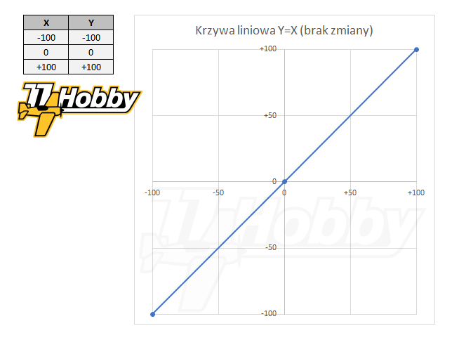
In OpenTX, the X axis is respresenting the curve input, for example the aileron stick. The Y axis represents the output, e.g. the servo on one of the ailerons. The curve performs the linear function Y = X.
Because the curve is fully linear, each X value corresponds exactly to the same Y value, i.e. the stick in the -50% position will give -50% output. So the curve does nothing and there really is no sense in using such a curve. Nevertheless, for educational purposes, it is worth starting with such a simple example.
Example 2
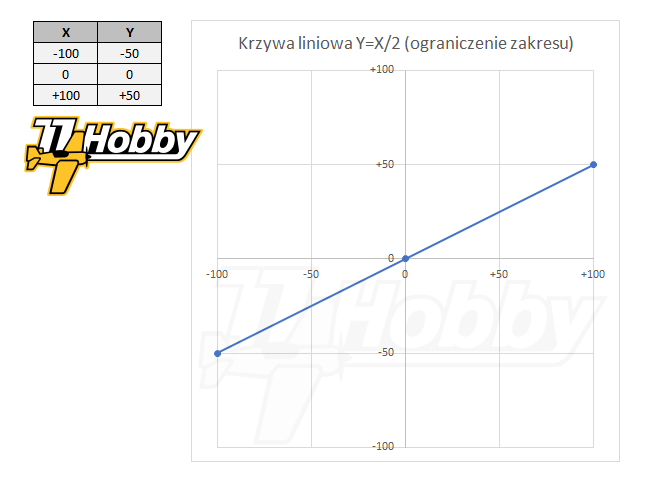
In this example, the stick in the -50% position (X axis) at the curve output (Y axis) will give a value of -25%; for the value of X = 100%, the output Y will show 50%. Thus, the curve defined in this way restricts the operation of the aileron stick by half. As a result, the servo connected to the channels of the output mixer, to which such a curve would be assigned, would move only in the middle of the range in each direction. Such a defined curve can be used, for example, to implement the so-called dual-rates, i.e. limiting the operating range of a given steering surface.
Also in this case, the same effect can be achieved simply by assigning 50% weight to the channel. The output effect will be the same. But what if we want to implement, for example, the so-called expo function, i.e. that the stick was less sensitive in its middle range, allowing for precise control of the model, but nevertheless that the servo worked in full range, smoothly accelerating the movement outside the center area of the stick operation?
Such functionality can be implemented only with the help of Expo curves:
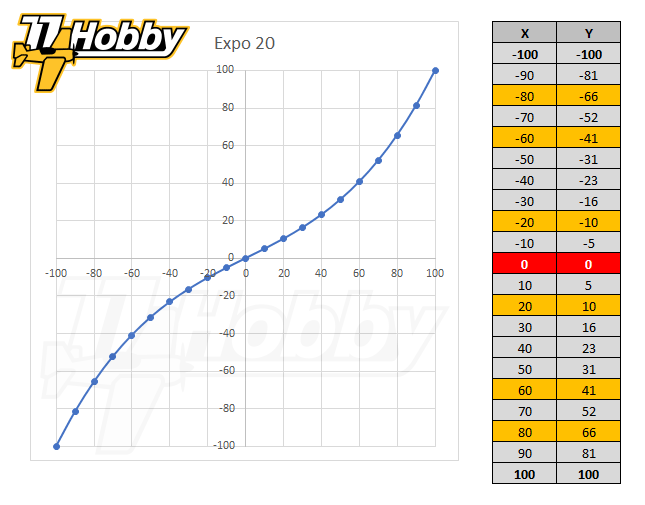
Not only the above curve is not linear, it is also smoothed, so the curve passes through certain defined points, but between them it adopts changing values smoothly. Thanks to this servo control will be precise near the center of the stick (i.e. for deflecting the pole to 20%, only 10% appears on the output), but at the same time it will be possible to use the full servo / channel range, i.e. for extreme deflections, the output values will still reach ±100% respectively. The transitions between the individual points will be smooth, so there will not be a step change in the servo movement at any moment, although the servo response will be faster as the min / max limits are reached.
Note: the expo curves are pre-defined in OpenTX (and many other systems), i.e. you do not need to configure them manually in the Curves tab. You can simply choose an expo curve as assigned to a rule in the Inputs or Mixes tabs, and then specify a numerical value determining how much the expo curve is to modify its input. The higher the numerical value of the expo, the greater the modification. Below is an example curve for Expo 40:
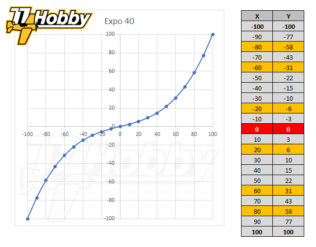
In comparison to the Expo 20 curve (the above, previous graph), the Expo 40 curve is even more precise near the center, so the stick moves around the center will translate into even more delicate changes at the curve output (for X = 20, Y is only 6). Nevertheless, the output of each pre-defined expo curve will work in the full range, i.e. for the extreme positions of the pole, it will reach ±100%.
You have to be careful, because for high expo values (i.e. 70-80) in the center the stick will work very precisely and gently, but outside the center will rapidly change to values close to ±100%. This behavior will cause a sudden reaction of the model, which may not necessarily be expected or desired.
Example 3
Consider the third and last example in which we define a curve that realizes the functionality of the airplane’s flaps. Let us assume that the raised flaps are carried out in the central position of the servomechanism (so the channel value is 0%), and the maximum flap release requires the servo to move fully to the left (channel value -100%). At the same time, we want the control to be carried out with the slide potentiometer, from the upper position of the slider (raised flaps), to the lower position (the flaps fully released).
Translating this into specific values of the axis of the curve:
- on the curve input (X axis) we have a potentiometer working from +100% (upper position of the slider, raised flaps) up to -100% (bottom position of the slider, flaps fully released)
- on the curve output (Y axis) we want to achieve values from 0% respectively (the servo is in the central position, the flaps raised to -100% (servo in the leftmost position, the flaps fully released)
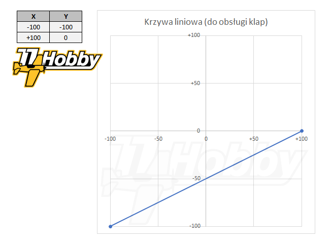
The curve shown above, assigned to the flap control channel, will realize the wanted relation between the movement of the slider and the flap servo movement. To confirm this, it is enough to trace the values on the X axis (movements of the stick) and the corresponding values on the Y axis (curve output / servo horn movement).
It is good to understand how the curves work, because many functionalities can only be realized using curves or using curves is easier than using other methods (usually combinations of weights, offsets, reversals, etc.).
Understanding how curves work, let us analyze how specific curves defined in our project work and are used.
Analysis of defined curves
Curve CV1 – TH (Throttle Hold)
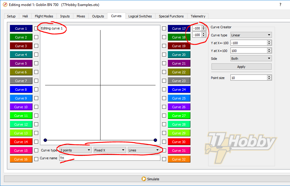
It is a two-point curve, which – if assigned to CH3 channel – will be independently of the input state of the channel to which it is assigned providing output value -100% (possibly shifted by an additional parameter so that the nitro engine runs at idle if we want it to).
It is worth noting that in the case of the “Fixed X” curve, we only define values on the Y axis (-100% and -100%, i.e. the flat line at the very bottom of the chart). The corresponding X-axis values in the case of the “Fixed X” curve are pre-defined implicitly (distributed evenly depending on the number of curve points, in our case -100 and +100, so as to cover the full range of the X-axis).
The CV1 curve is not de facto used in our example configuration. As we remember, the rule responsible for the Throttle Hold functionality looks like this:
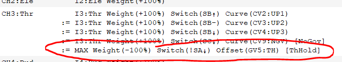
If we wanted to use the CV1 curve for the same purpose, this rule would look as follows:
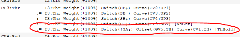
giving exactly the same effect.
I defined the TH curve and gave it as an example only to show that there are usually at least a few ways to achieve the desired effect in OpenTX. Often you can not say which way is better. They are just different and it depends on us, which way will be more convenient, easier to use, better reflecting intentions, etc.
Throttle Hold and Idle-Up features of helicopter models are traditionally configured using curves. For this reason, at least for some people, it can be a more natural way than setting up using the special MAX value and weight assignment.
Curves CV2, CV3, CV4 – UP1, UP2, UP3 (Idle-Up 1/2/3)
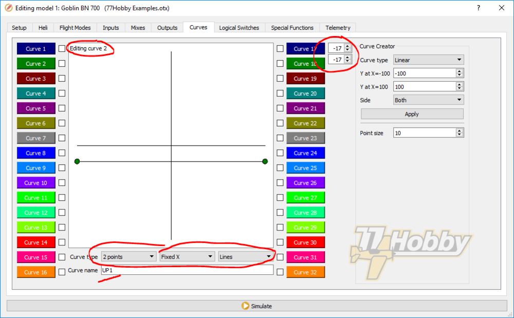
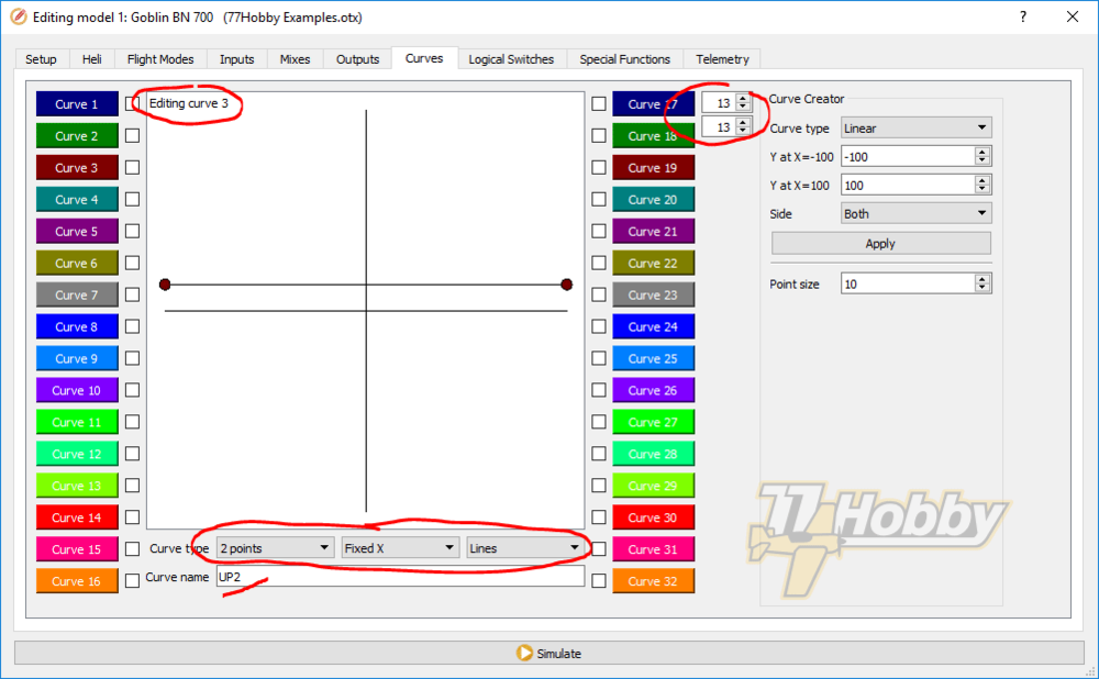
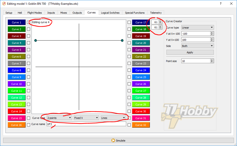
These curves are used to determine the governor’s operating speed in the Brain 2 controller (or any other similar governor in which individual modes of operation are activated by means of the Throttle channel level).
All three curves are flat, resulting in constant values in the scale -100% / +100% corresponding to CH3 (Throttle) channel value ranges, for which the Brain 2 governor will be activated:
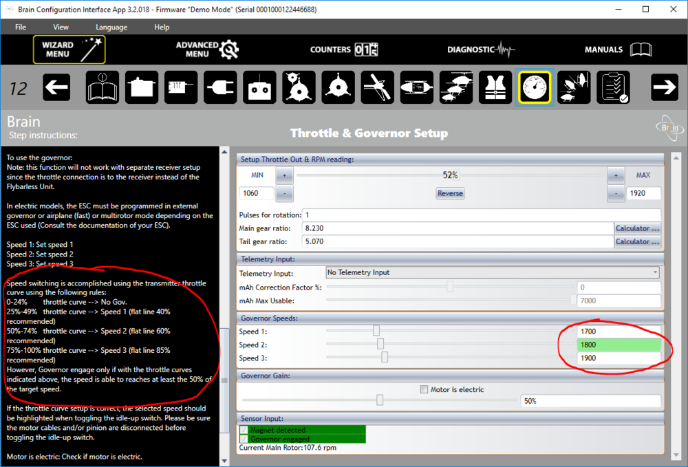
(earlier in this article I already covered the conversion from -100% / +100% scale to 0% / 100% scale)
As a reminder, the UP1 / UP2 / UP3 curves are activated in these mixer rules:
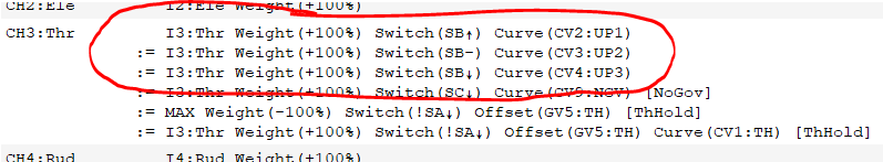
Depending on the range in which the output value of the channel to which these curves are assigned (CH3), the governor of the Brain 2 controller will control the engine throttle so as to keep the given main rotor speed of the helicopter as accurately as possible.
Curves CV5, CV6 – PT1, PT2 (pitch)

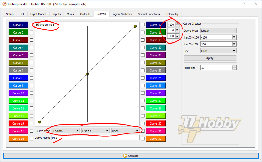
The PT1, PT2 curves determine the overall pitch of the main rotor blades of the helicopter. We use them in these mixer rules:
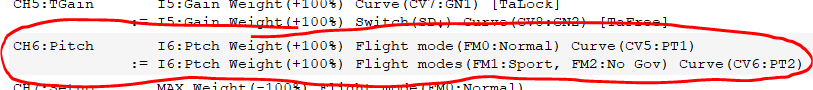
by assigning the PT1 curve when the FM0 (Normal) flight mode is selected. We assign the PT2 curve when the flight modes FM1 (Sport) or FM2 (No Gov) are selected.
The PT1 curve has non-linear characteristics. It causes the pitch of the blade to work in the full range on the positive side of the X axis (in practice from the middle position of the Throttle stick, to the position of the maximum throw of the stick). At the same time, with the Throttle stick moving downwards, the blade pitch will be limited (maximum -60% on the Y axis, for X = -100%, when the Throttle stick is completely down).
Curves CV7, CV8 – GN1, GN2 (P gain for tail rotor in “tail lock” and “tail free” modes
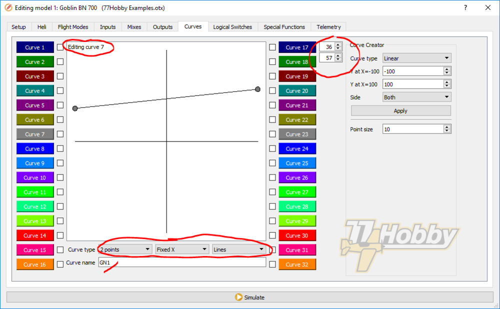
In our example, we want the potentiometer S2 to regulate the value of the P gain for the tail rotor, and the SD switch to determine the “Heading Lock” or “Tail Free” operating mode.
In Brain 2 controllers, the gain value is proportional to the channel value (standard CH5). What is also important, the operating mode is determined based on the channel value:
- from 0% to +100% – gain from 0 to 100, in “Heading Lock” mode, i.e. a standard mode for sports and 3D helicopters.
- from 0% to -100% – gain from 0 to 100, in “Tail Free” mode, i.e. in which the model is subjected to aerodynamic forces and deflects (rotates in the main rotor axis) in accordance with them. This mode is still used in the case of scale models, because it more naturally reflects the behavior of a real helicopter.
In the simplest configuration, we could simply assign a potentiometer in the mixer as input CH5. Then, turning it to the right, we would have a range from 0 to +100% on the channel output, and from 0 to -100% on the left turn.
This solution, however, is not optimal and almost certainly would cause great difficulty in controlling the model. First, it would be very difficult to set and precisely change the gain value. Secondly, changing the “Heading Lock” / “Tail Free” mode would require going through all intermediate values, i.e. a change from +50 to -50 would have to pass all values in between (by doing that in some point in time we would have gain equal to 0, for sure causing model control problems).
Therefore, in the mixer configuration I used the following CH5 channel definitions:
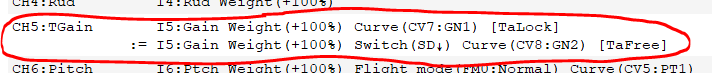
Normally the first rule is active, assigning a curve GN1 to the channel. The GN1 curve causes that when the potentiometer S2 (previously defined input I5:Gain) is rotated all to the left, the channel value as read by Brain 2 is 40%. When the potentiometer S2 is turned to all the right, the gain value in Brain is 60%. In the middle position, the gain value is 50%.
Note: The actual min / max values of the curve are 36% and 57% respectively, but this is because min / max values of OpenTX channels (988μs and 2012μs) differ slightly from the values expected by the Brain 2 controller. Therefore, the min / max values of the curve should be selected experimentally, observing gain values read by Brain 2.
Thanks to the curve defined and assigned to the channel, the full turn range of the potentiometer S2 causes relatively small changes in the gain value (maximum by 10 in each direction). By such configuration, high accuracy of changes is ensured, so. the potentiometer must be significantly rotated to cause the gain value to change by 1. If the need was to be even more accurate, the curve min / max values can be adjusted so that the change in each side is even smaller, i.e. by 5 (so the effective gain range would be 45-55%).
Values of the GN1 curve remain always positive, so Brain 2 works in “Heading” Lock mode.
Theoretically, you could use the same GN1 curve, only assigned to the channel with -100% weight, to switch to the “Tail Free” mode. However, the aforementioned mismatching of the channel edge values (and mismatch of the middle value) causes that the switching configured in this way would not hit the same value, i.e. +45% after switching could be read by Brain 2 as -44% or – 46%. It could be perfectly matched the min / max values and the center value, but it is more convenient to define the GN2 curve:
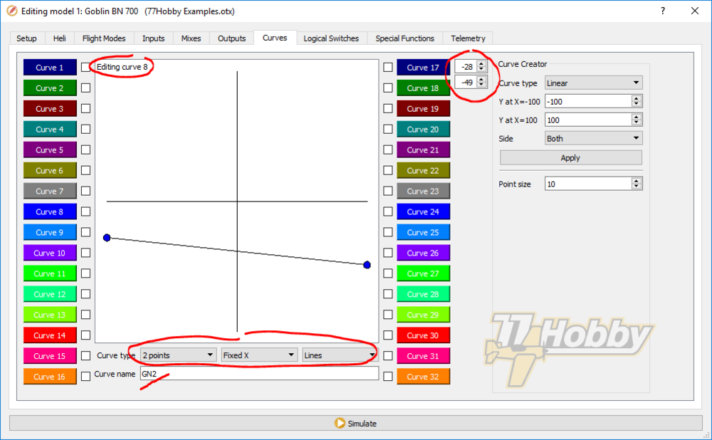
very similar to GN1, but in boundary values chosen experimentally so that for each positive value, after switching the SD switch down, the gain value remained exactly the same, changing only the sign to negative (remember that negative gain values activate the “Tail Free” mode). Such a configuration allow us also to have different gain ranges for “Tail Lock” and “Tail Free” modes.
Curve CV9 – NGV (No Governor)
The NGV curve is activated in the mixer by the SC switch ↓:

which simultaneously controls the flight modes, in the SC position ↓ deactivating the governor in the Brain 2 controller:
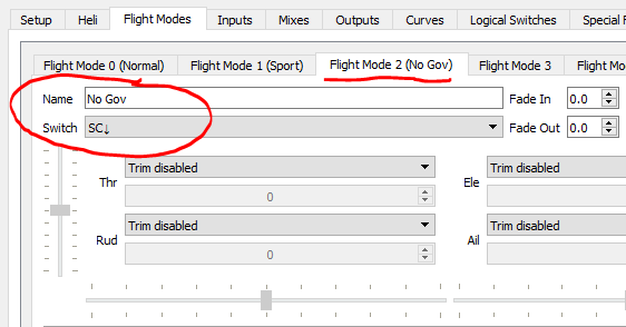
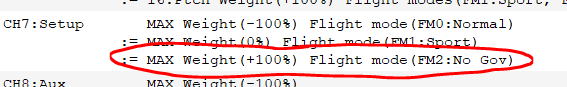
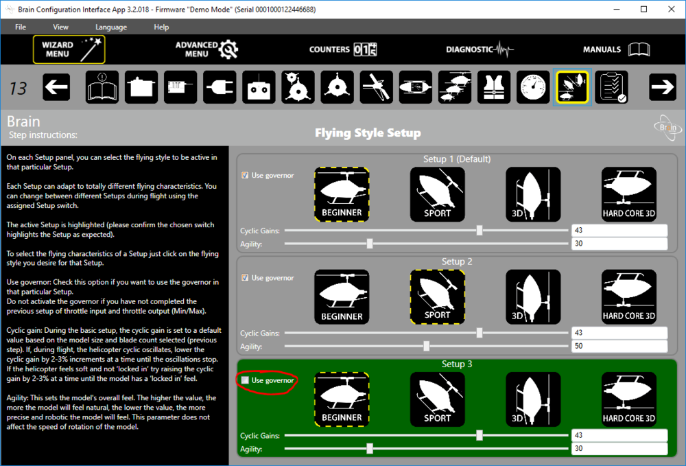
The combination of both configurations (activation of the throttle curve on the CH3 channel and deactivation of the governor in Brain 2) will result in directly controlling the engine throttle in accordance with the defined curve. In the central position of the throttle stick (X = 0) the value of the throttle channel (CH3) will be Y = -17%. As the throttle stick moves up or down (controlling the pitch angle of the main rotor blades), the channel value will gradually increase to Y = 100% (gas throttle fully open, providing maximum power at the maximum pitch angle of the blades).
Note: NGV curve – although defined as “Smooth” – in the OpenTX Companion is not graphically shown as having smooth transitions. This is due only to the limitations of the OpenTX Companion and may be revised in future versions. But in reality (in the transmitter) the course of the NGV curve is smooth, with values smoothly varying from -17% to +100%, without any “sharp” edges:
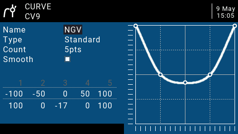
Of course, individual values of points on the Y axis of the NGV curve should be selected for a particular motor, according to the desired power dissipation characteristics and the assumed engine revolutions. If necessary, you can add more points or limit their number. In the extreme case, it could even be a two-point, flat curve.
OpenTX Companion – Special Functions tab
To keep the order, I should discuss the Logical Switches tab here. However, logic switches defined in our example are mainly used in special functions, so I will discuss them in this context now.
With the help of special functions, you can carry out many different actions. For example, overwrite the output value of a given channel, play audio files stored on the SD card, read telemetry parameters as voice messages, reset or set telemetry parameters, enable or disable logs, change global variables and much more.
In this article, I will not discuss all available special functions. I will focus only on those that are actually used in our example configuration.
The screen of the special functions tab is organized in columns:
- # (SFn number)
- Switch – A physical or logic switch that activates the special function. The function is active as long as the switch assigned to it remains active. In the case of a physical switch it is active if it remains in a defined position, e.g. SA↓ (switch SA towards you) or – in the case of a logic switch – while the switch remains logically true (logic value “true / 1”).
Note: It is important to understand that the action will be active at all times when the switch remains active. It is not the case that the active switch will only trigger the action for a moment. I will discuss this in more detail later in the article. - Action – Selects the action that is activated by the switch. For example, to start reading the value of the given telemetry parameter.
- Parameters – Additional parameters defining the operation of the selected action. Some actions do not have to specify any parameters.
- Enable – Determines whether a particular line of special functions is active (checkbox Enable selected) or how many times and at what intervals a given action should be performed:
- periodically, every how many seconds (1..60 sec)
- without repetitions (No repeat)
- play once, not during the start of the radio
This last option is useful if you want a message to be read once, but at the same time you do not necessarily need to hear this message when you start the radio, if the switch is in the desired position at this time. For example: we want the SA switch in position ↑ to be confirmed by the “Throttle-Hold” voice message. At the same time, the position of SA↑ is the default position in which this switch should be located when starting the radio (activate / reset model or flight). We probably do not necessarily want to hear that the switch is in Throttle-Hold position when starting the radio, because it is its default safe position (we only want to hear the Throttle-Hold message when this switch is switched to this position from the Spool-Up position). In this situation, the option “Played once, not during startup ” is very useful.
As in other screens, each line of the special function screen defines one rule. However, the order is not very important here, unless we define rules assigned to the same switch and having the same action (action). In this case, the last active rule activated by the switch will be taken into account.
Analysis of special function rules
In our example, the following special functions are defined. Most of them are activated in a basic way, so in the specific position of one of the physical switches.
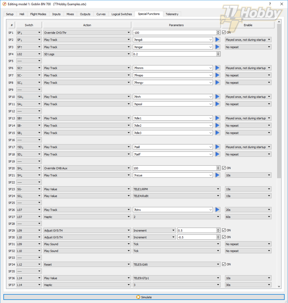
Some of the actions are activated by logic switches, which I will discuss every time these are being used in particular rules.
This is the definition of all logic switches used in the model – Logical Switches tab:
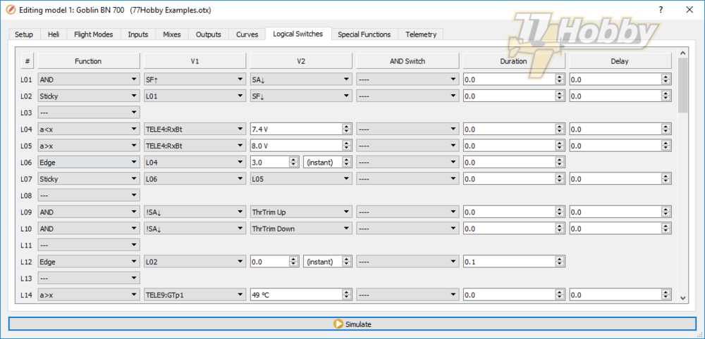
Special function rules SF1-SF4
We provide here two functionalities: ultimate shut-off of the engine, so-called Kill-Switch (CH3 channel to -100%) and activation of telemetry parameters logging on the SD card.
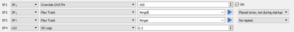
SF1: The motor cut-off (throttle full close) is activated by the SF switch ↓. It is implemented by the Override function, with the parameter -100. The effect is implicitly overwriting of the CH3 channel with the value -100%, regardless of the existing mixer functions (the special function of channel value override is performed at the end of signal processing in OpenTX), which closes the throttle valve of the nitro engine carburetor.
SF2: The function of voice playing the message defined in the 7engdi.wav (Engine disarmed) file is assigned to the same SF switch ↓. This message is read only once, but not when switching on the radio (when switching on the radio we check if the SF switch is in position ↓, so there is no point in confirming its default safe position).
SF3: Switching SF to position ↑ will automatically deactivate the rule overriding CH3 channel (the switch will no longer be in SF position ↓). Therefore, there is no need to define a dedicated rule that disables the overwrite function (the CH3 channel will be controlled by the mixer rules from now on). In the position of the SF switch ↑, we define the action of voice playing the message from the 7engar.wav file (Engine armed). This message is played once, but always, i.e. also when switching on the radio (if you accidentally ignore the switch status warning, the voice message will be played that the motor is armed).
The SF4 rule is activated by the L02 logical switch (defined in Logical Switches tab). Therefore, as long as the L02 switch will keep its “true” logical value, telemetry parameters will be logged, at a frequency of 0.2 seconds (so five times per second). All Telemetry parameters selected for logging will be logged to SD card (you can chose which parameters should be logged by selecting checkbox “Logs” in the Telemetry tab).
The L02 logic switch (and also L01 being a part of it) is defined as follows (in the Logical Switches tab):

I already described how the switches L01 and L02 works, when I described the triggering of the timer (meter) responsible for measuring the length of the flight. Let me just remind you that the L02 switch is activated when the Spool-Up (SA↓) is started for the “armed” engine (SF↑) for the first time, so in fact starting the model’s rotor. Thanks to the “sticky” function, the L02 switch remains active (logical value “true”), regardless of how many times we will then switch between Spool-Up / Throttle Hold (with switch SA). L02 will be deactivated only when you “disarm” the motor with the SF↓.
Using the logical switch L02 defined in this way, we control the time of the meter measuring the exact actual flight time, so from the first start of the main model rotor (Spool-Up), until the engine is stopped after landing. In the meantime we can perform any number of Throttle-Hold / Spool-Up cycles, i.e. to practice helicopter auto-rotation landings.
I use the same L02 switch in the special function rule SF4 to activate the logging. After all, we usually want to log flight parameters, and not necessarily what happens when we carry a model to its take-off position.
Special function rules SF6-SF8, SF10-SF11, SF13-SF15, SF16-SF18
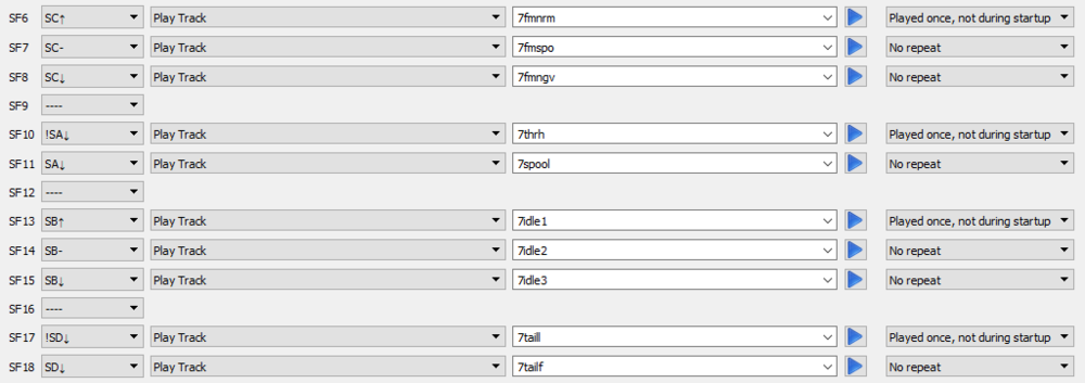
These are very simple rules that cause the reading of voice messages confirming the switching of physical switches to specific positions, in accordance with the assumptions of our project. These are:
- SF6: Flight mode normal
- SF7: Flight mode sport
- SF8: No-governor
- SF10: Throttle-Hold
- SF11: Spool-Up
- SF13: Idle-Up 1
- SF14: Idle-Up 2
- SF15: Idle-Up 3
- SF17: Tail Lock
- SF18: Tail Free
Default switch positions, checked when the radio is started, are enabled in Special Functions tab with the option “Played once, not during startup”. Other voice announcements are enabled with the “No repeat” option.
Special function rules SF20-SFS1

The momentary switch SH is designed to activate the “rescue” function of the Brain 2 controller (controller AUX channel, controlled by the CH8 channel).
In the mixer rules, using the MAX function with reversed weight, we set the CH8 channel value to -100%. This corresponds to the default, inactive “rescue” function.
We could change the CH8 channel value in the mixer, but because the “rescue” function should always work, I prefer to activate it using the “Override” function of the special functions.
The SF20 rule, when holding the momentary switch SH, overwrites the CH8 channel value, activating “rescue” in the Brain 2 controller.
At the same time, rule SF21, plays the appropriate voice message “Rescue” (when the switch is activated and then every 10 seconds, as long as the switch SH remains in the position SH↓).
Special function rules SF23-SF24

In the SG- and SG↓ switch positions, every 15 seconds, the values of selected telemetry variables are played as voice message. I wanted to have the engine RPM and the receiver supply voltage (RxBt).
Special function rules SF26-SF27

The SF26 rule is a simple rule that plays low battery voltage voice alarm (“RX Battery Low”). At the same time, because this is a very important information, the SF27 rule activates the second alert, as a haptic vibrations (different types of vibrations are assigned numbers from 0 to 3). Thanks to this, if for some reason we do not hear a voice message, the vibrating radio will also let us know that something critical is happening.
The voice message is repeated every 20 seconds and vibration alarm every 60 seconds.
The rules SF26 and SF27 are simple and do not require any special comments. Both rules are activated using the L07 logic switch, which will devote a bit more attention to:
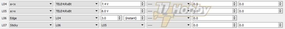
The L07 switch could be defined like the L04 switch, so it would become active when the voltage drops below a certain level (in the example, parameter RxBt and level 7.4V). The problem with such a definition of the locical switch detecting too low voltage is that at battery voltage in the area of 7.4V it will be repeatedly and in short intervals activated, depending on the momentary battery load (when the voltage will oscillate around 7.4V). As a result, instead of a voice message every 20 seconds and vibrating every 60 seconds, we would have many, often immediately occurring, voice messages and vibrating alerts. It would fulfill its function, but it would not be too elegant. In OpenTX, it can be configured much better.
The solution is to test the voltage for some set period of time. Only if the voltage is continuously lower than the set threshold for this fixed time, then the alarm is triggered. Once triggered, the alarm should not be reset, even if the voltage temporarily returns to the level slightly above the threshold (in our example 7.4V).
A detailed discussion of logic switches is not the subject of this article. But in short, each logical switch screen rule includes:
- Switch number # (L01-L064)
- Function (logical AND, OR, XOR, various functions of parameter comparison, i.e. a<x, special functions Edge, Sticky, Timer)
- V1 (Value 1)
- V2 (Value 2)
- Switch AND
- Additional parameters “Duration” and “Delay”
Depending on the selected function, the values of V1 / V2 and other parameters may have different meanings. For details, I have to send it back to the OpenTX documentation, but I will try to explain the operation of the switches that make up the final functionality of the L07 switch, which we use in special rules SF26 / SF27.
Logical switch L04
This switch starts the path leading to the activation of switch L07.
Logical switch L04 uses the comparison function “a<x”, where “a” is defined in column V1 (Value 1), and “x” is defined in column V2 (Value 2). In our example, as V1 we give the telemetry parameter RxBt, and in V2 we define the threshold value 7.4V.
The L04 switch will be activated each time the voltage drops below the set threshold of 7.4V. As I wrote, it will happen many times, when close to the threshold voltage, which is not really desired.
Logical switch L06
(in the meantime deliberately I omit L05)
This switch uses the Edge (instant) function to test whether the switch set in column V1 (Value 1) remains active for the time defined in column V2 (Value 2).
If this happens, logic switch L06 will become active for a while. This is not very important, but in this case “for a moment” means about 30 ms, as the “Duration” parameter is set to zero (about 30 ms is the shortest possible time of the Edge triggered by the function). Such a short pulse is however sufficient for use in the next rule, when defining our target logical switch L07.
Logical switch L07
The definition of the L07 switch uses the sticky function, which works by permanently activating the L07 switch when (at least for a moment) the switch set in column V1 (Value 1) is active. The L07 switch will remain active until (also at least for a moment) the switch set in column V2 (Value 2) becomes active.
In column V1 (Value 1) we use the previously defined switch L06, which becomes active when the switch L04 remains active for 3 seconds.
As a result, we obtain the desired functionality: the L07 switch becomes permanently active if the battery voltage falls below 7.4V for at least 3 seconds. The L07 logical switch will remain active, even if the voltage for a moment returns to a level slightly above 7.4V (i.e. if 3 seconds is not enough time and the voltage temporarily increases as a result of a decrease in the current load).
As a result of all above, activated by L07 logical switch the voice and haptic vibration alarms messages will operate stably, without unnecessary fluctuations caused by voltage oscillations around the set 7.4V threshold.
There remains the question how to deactivate the L07 switch after replacing or charging the battery in the model. This happens automatically when the radio is restarted, when the model is activated or by resetting the flight manually in OpenTX.
The software deactivation of the L07 switch could therefore be omitted. However, for convenience – if we replaced the battery in the model, but did not reset the flight – the L07 switch is deactivated when the switch defined in column V2 (Value 2) becomes active even for a while. In the column V2 of switch L07, we provide the switch L05 that becomes active when the battery voltage is exceeding the given threshold for a moment (defined as 8.0V). In practice, this situation (return voltage from around 7.4V to above 8.0V) can only happen after the battery has been replaced / charged. As a result, after battery replacement, the L07 switch is deactivated and remains in this state until the voltage drops below 7.4V for at least 3 seconds again (3 seconds is the time that works in my opinion and detects the low battery voltage well, but nothing prevents to extend this time slightly, i.e. up to 8-10 seconds, if needed).
Special function rules SF29-SF32
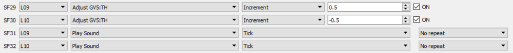
By means of these two rules, we implement the function of regulating the Throttle-Hold servo position (idling engine).
We want the Throttle-Hold position to be adjusted only when the Throttle-Hold switch is active (SA switch in a position other than down, so !SA↓). Thanks to this, we will not accidentally change the Throttle-Hold level during the flight, which could cause the engine to turn off when purposely switching it to idling, i.e. during the auto-rotation exercise.
I would like to remind you that the Throttle-Hold servo throttle level value is stored in the global variable GV5:TH (this variable is used in the throttle mixer ThHold rule).
The first two rules of SF29 and SF30 regulate (adjust) the TH variable, increasing it by a given value, 0.5 and minus 0.5 respectively. Thanks to this when activating these rules, the variable TH will be slightly increased or decreased by adjusting the engine idle speed.
In addition, the rules SF31 and SF32 plays one of the standard, short sounds (Tick), so that the manipulation of the throttle trim is signalled by sound. (Remember that the trims as such are turned off on the Flight Modes tab. Here somehow we implement a special functionality, regulating Throttle-Hold only when the SA switch is in a position other than ↓, therefore we have to take care of the sound signals.)
Normally, to activate the above rules, we would assign to them, respectively, ThrTrim Up and ThrTrim Down switches. However, we use logic switches L09 and L10, defined by rules in the Logical Switches tab:

Thanks to the use of the AND logical function the L09 and L10 switches activate (they assume the “true” logic value) only when the SA switch is in position !SA↓ (not towards you, in other words when Throttle-Hold is active) and – in the same time – when the throttle trim is pushed up or down (respectively ThrTrim Up or ThrTrim Down).
If the SA switch is in the down position SA↓ (Idle-Up, the motor is running at high speed), pushing the trim will not activate logic switches L09 or L10. As a result, the value of the TH variable will not be modified during the flight.
The rule of the special function SF34

In the example model we use a GPS sensor, which, among other things, gives the altitude as a telemetry parameter GAlt.
However normally GAlt altitude is given relative to the sea level, which is not very useful in our application. Therefore, at the moment of the start, the GAlt value must be reset. From the moment of reset, the height relative to the place where the reset was performed will be indicated by GAlt parameter.
To reset GAlt, the Reset function must be activated temporarily. It is important that the Reset function will be performed temporarily and once. Activating this function with a normal switch (left in a given position, i.e. Idle-Up or Kill-Switch) would cause a continuous reset of GAlt and consequently logging of zero altitude for a whole duration of the flight.
It would be possible to do the reset with a dedicated, ordinary switch, but you should always remember about it and switch it off manually after each reset.
Thus why the logic switch L12 comes as a help:
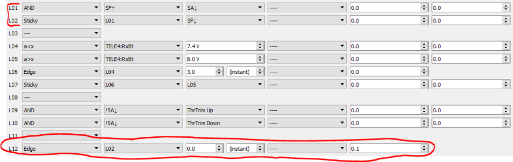
The L12 switch uses the Edge function, which in a given configuration triggers a one-time impulse with 0.1 second of duration. The pulse triggering is instantaneous, in the very moment when the L02 switch defined in column V1 (Value 1) becomes active. After triggering, the L12 switch is active only as long as the pulse lasts, so one tenth of a second.
We used the L02 switch earlier and then discussed its operation in detail. Therefore, just to remind: it becomes active at the moment of the flight start (Kill-Switch + for the first time Idle-Up) and turns off only after you use the Kill-Switch to shut the engine after the flight.
As a result of the above we get such an effect: when the model starts (first use of Idle-Up), the L02 switch becomes active and simultaneously activates the L12 switch, but this one only once and only for 0.1 seconds (Edge function). This short-lived L12 activity resets the GAlt telemetry parameter, which from then on shows the altitude relative to the take-off position of the model.
Special function rules SF36-SF37

These two simple functions implement an alarm about too high engine temperature (GTp1 telemetry parameter of the FrSky Gas Suite sensor). After activation, the special function SF36 reads the temperature value by voice every 10 seconds and SF37 activates the vibration alarm every 30 seconds.
Both functions are activated by usage of the logic switch L14:

Switch L14 (similarly to switches L04 and L05) compares the value of the monitored parameter GTp1 with the set threshold value of 49°C.
Due to its specificity, the temperature of the motor does not oscillate around the threshold, but when it exceeds it, it usually stays for a longer time. Thus, in the L14 definition it is enough to compare a>x (where a = GTp1 and x = 49°C), and we do not have to use additional variables as in the case of L04-L07.
OpenTX Companion – Telemetry tab

In the Telemetry tab OpenTX telemetry sensors are defined, which we use in various places of model configuration.
In OpenTX 2.1 and newer, the sensors are detected dynamically, so the best method to put them into configuration is to connect everything in the model (receiver and sensors) and run the sensor discovery procedure on a radio. Only then connect radio to the computer, import the configuration (with detected sensors) and start the remaining OpenTX Companion configuration process.
FrSky Smart Port telemetry configuration is described in great detail in another FrSky Workshop article – OpenTX 2.1 Telemetry, so I will not repeat everything here.
Disclaimer: I have made every effort to ensure that the article is professionally and reliably prepared. However, use it at your own risk.
All rights reserved. Copying or distribution, in whole or in part, is only permitted with the consent of the author.