
The analog port of FrSky receivers is very useful, and at the same time probably an underestimated option offered by FrSky receivers. Until now, not all receivers were equipped with an analog port. However, all receivers of the new FrSky Archer series will be equipped with such a port, so it is probably worth taking a closer look at its capabilities.
This English article is slightly polished version of an automated translation. Thus please do not expect Shakespeare English here, but we do hope it is usable enough.
All FrSky telemetry receivers have at least one, internal analog port, usually detected in the OpenTX telemetry system as RxBt. It indicates the receiver’s own supply voltage, which is especially useful in the case of powering the receiver and servos directly from a 2S battery (without BEC).
Some receivers (almost all in the Archer series) are equipped with external analog port, usually labeled A2 or AIN.
Analog port measures the voltage in a range of 0-3.3V. Seemingly this is not a very useful range, but it is enough to use a simple voltage divider to measure any voltage in the model quite accurately, even a large 12S battery voltage.
Some Archer series receivers (eg R10 Pro) have an analog port that can directly measure voltage in the range of 0-36V. In this case – if the measured voltage is within the range – there is no need and no use for a voltage divider. If the voltage measured by such receivers is higher than 36V, a divider reducing the voltage slightly below 36V should be used.
WARNING: only some Archer receivers can measure voltage up to 36V directly, so you must always check it in the receiver’s specification.
Such a voltage divider (sensor) can be made alone or bought ready to use. FrSky offers a universal voltage divider for LiPo batteries up to 5S – FrSky FBVS-01 voltage sensor.
Regardless of whether we buy the sensor or make it ourselves, it should be connected to the receiver in the same way. Minus wire of the sensor (divider) to the GND pin, and plus wire to the A2 pin of the receiver.
The simplest voltage divider consists of two resistors. The values of these resistors should be selected so that the voltage at the A2 pin (relative to GND) never exceeds 3.3V. At the same time, the current flowing through port A2 should be minimal, so it is better to use slightly higher resistor values (in the below examples we will use kΩ resistances).
Wiring diagram
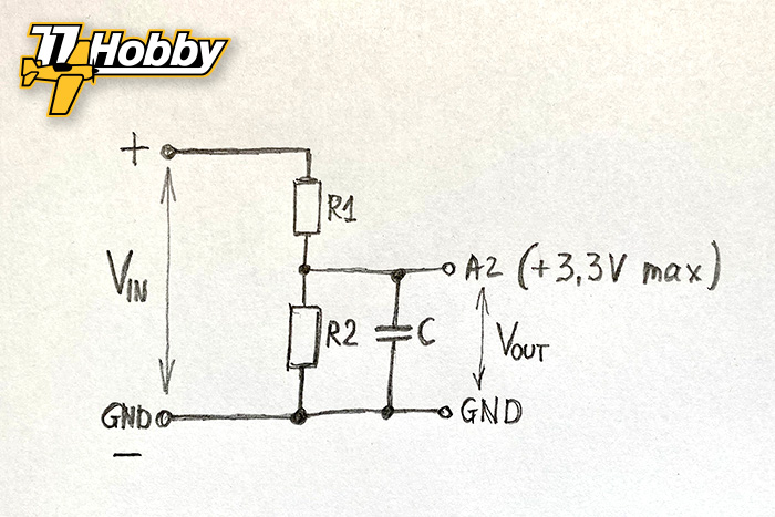
- Vin is the input voltage, e.g. of the main battery pack in the model
- Vout is the voltage fed to the A2 analog port (must not exceed 3.3V)
- R1, R2 are the voltage divider resistors
The diagram shows an optional C capacitor. The capacitor is optional, as temporary voltage drop filtering can be implemented in OpenTX. However, if there was noise in the voltage readings from the divider, such a capacitor can help eliminate them.
If we want to connect a capacitor, a ceramic 50-100nF will do the job.
Selection of resistors
The output voltage V out can be easily calculated from the formula:
Vout = Vin * R2 / (R1 + R2)
Now all you must do is choose the right resistor value. Resistors are produced in so-called series in which their specific, commercially available values are available.
It is worth choosing the values of the resistors to leave some safety margin, so that the voltage Vout is around 3.1-3.2V (slightly lower than 3.3V). At the same time, there is no reason to lower the voltage too much, because then we lose the measurement resolution.
Below are examples of resistor values for LiPo cell packs using the popular E24 series resistors:
| Pakiet LiPo (Vin) | R1 | R2 | Vout |
| 1S (4.2V) | 2.2k | 6.8k | 3.17V |
| 2S (8.4V) | 10k | 6.2k | 3.21V |
| 3S (12.6V) | 10k | 3.3k | 3.12V |
| 4S (16.8V) | 11k | 2.5k | 3.11V |
| 6S (25.2V) | 15k | 2.2k | 3.22V |
| 8S (33.6V) | 15k | 1.5k | 3.05V |
| 12S (50.4V) | 15k | 1k | 3.15V |
Typical resistors have an accuracy of 5%. They will work in our application (we assume an error margin, and the sensor will have to be calibrated), although 2% or even 1% resistors would work better. They are more expensive, but we are constantly talking about the amounts expressed in pennies. The power of the resistors does not matter. The smaller the size, the better (we will solder them directly on the cable, without any printed circuit board).
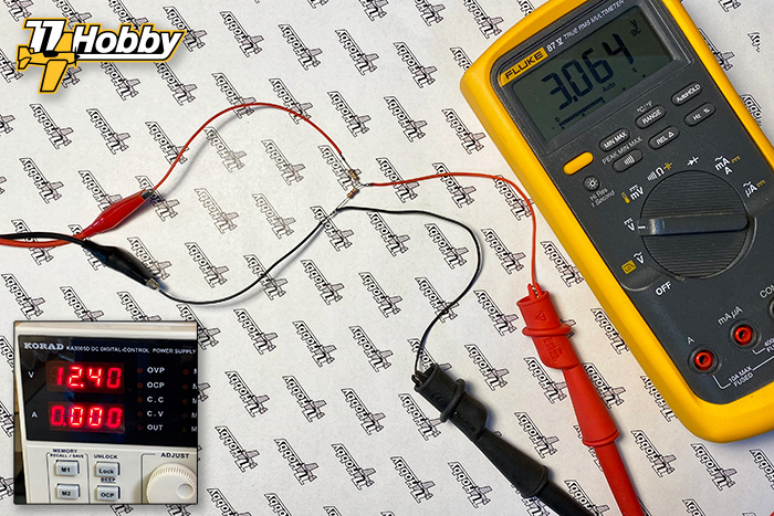
Practical example
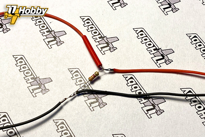
This is how soldered resistors look like in a test circuit. At the input we have a fully charged 3S (12.6V) battery, and at the output – almost according to calculations – 3.06V (the input voltage was mistakenly set to 12.4V).
NOTE: The absolute maximum voltage Vout is 3.3V
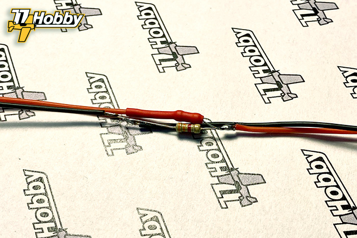
Soldering could be done a little closer to the resistors. Here, for demonstration purposes, we have kept larger gaps:
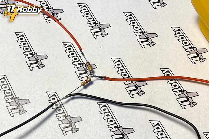
After checking the correct operation, we isolate the positive wire from the Vin side (for soldering similar to ours, there is no need to isolate the positive wire from the Vout side, because after folding it has no way to short to GND):
Fold the resistors together to fit it all into a heat shrink:
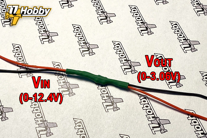
The final result
This is what the ready sensor looks like (in our example, built for a LiPo 3S battery), converting the input voltage from 0-12.4V to a proportionally reduced voltage in the 0-3.06V range.
Configuration and calibration in OpenTX
After connecting to the receiver, the sensor should be detected in the OpenTX telemetry system. Since it is an analog sensor, it should also be calibrated to show accurate values corresponding to the actual voltage at the divider input.
The OpenTX 2.1 Telemetry is a detailed article describing, among others, the processes of sensor detection and calibration.
In the OpenTX – nitro helicopter configuration (and not only) article we’ve described how to configure an analog sensor in such a way that it does not respond to momentary voltage drops.
A small, great port
The analog port is simple. However, it gives a lot of opportunities to build your own sensors. In this article, we have built the simplest voltage sensor, but people with some basic electronic skills will easily build other sensors, e.g. current sensor, various mechanical sensors, etc.
Anything that can be converted to 0-3.3V can be connected and recognized in OpenTX telemetry through the receiver’s analog port.
In the article Ports not only FrSky we describe other types of ports widely used in RC hobby (PWM, CPPM, SBUS, etc.).
Smart Port voltage sensors
This is not directly related to this article, but it is worth mentioning that dedicated Smart Port sensors – FrSky FLVSS and MLVSS are better suited for measuring voltage of LiPo / LiIon packs . Not only are they more accurate, but they measure the voltage separately for each cell in the packet, enabling you to set an alarm e.g. for the cell with the lowest voltage. This is an especially useful feature that allows early detection of a faulty battery pack.
Hello,
Nice article.
Please have a look at the following case.
In order to measure the current from my rc plane E motor I use the acs758 50Amp.current sensor.
First I used the openXsensor set-up with the arduino board. Is not working. ( needs the usb to start???????)
Then I found out that the acs758 output is analog. Vout is Vin/2 + 40mV per Amp.
So I measured as output from 2,5 volt to 3,8 volt. Looks ok this signal. This is 4,95/2 + mv*Amp
But connecting the acs785 output to the analog input of my FrSky archer R6 receiver ana input the telemetry gives 1,7V and stops at 1,8V??? I tink this somewher related to the 0-3,3 volt input range from the R6.
I lowered the offset by 1,7V still only 0,10Volt to be measured.
The R6 is feed from the bec and is 4,95V according the telemetry.
May I ask where do I,am make a mistake?
I would like to measure the current direct out the acs785 instead of using the sbus feature from openXsensor with the arduino.
Any help is much appriciated.
Kind regards,
Theo