
There are many popular lost RC model finders available on the market. They are usually simple and inexpensive devices, activated by signal loss or inactivity on RC channel which they are connected to, after some pre-defined time.
They work, but they are rather cumbersome in use, as they often activate themselves in unwanted conditions, often on the ground, before a flight or after landing. They are also dependent on model’s power source and having small buzzers.
Thus I decided to develop my own lost model finder – MAK RC Model Finder (MRCMF) – under following assumptions:
- Loud, high quality buzzer
- Alarm triggered only if whole device is “armed” first
- Controlled by standard RC PWM signal (like servo)
- Possible to be powered by its own battery, not dependent on batteries of the model (with voltage monitoring and alarm, to limit odds of complete battery drain)
- Microprocessor based, firmware upgradeable
- Dedicated to rather large scale models
In short words the MRCMF should armed before a flight and disarmed after. It is meant to be done along with kill (safety) switch of the engine. Alarm can be activated only when armed: manually, by fail-safe function or by lost PWM signal from the receiver


Connection
The MRCMF should be connected to standard PWM port of RC receiver, using standard 3-wire JR connector (+5V from the receiver is not connected anyhow) and to 3S LiPo battery. During startup PWM signal should be set to the middle (0%) – see technical specification below for PWM states. If during the startup PWM signal is not at 0%, or not present at all, the device will signal it by flashing both LEDs and beeping every 1s and will not enter normal working mode until PWM signal state is corrected (present and in the middle).
During startup the MRCMF checks if voltage calibration is in acceptable range. If it is not, then both LEDs will flash alternately every half a second and beep will be sounded every second, awaiting calibration. Regardless of that the calibration is recommended after first soldering and flashing the firmware.
Operating modes
Normal (disarmed) mode
After successful initialization, MRCMF will signal its readiness by flashing LEDs (green-red-green) and will enter NORMAL mode. Normal mode can be also triggered as a return from ARMED mode (disarm).
Normal mode operations:
- blink green LED every 3s
- wait for commands on PWM port
- check battery voltage and enter LOW VOLTAGE mode if needed
If detected PWM state is high (+100%), the device will enter ARMED mode. Best would be to configure it on the transmitter together with engine kill-switch, to have it controlled with one physical switch (even if the control of the MRCMF is probably provided via different RC channel of the receiver).
If detected PWM state is low (-100%) the device will lit both LEDs and wait 10 seconds, before entering CALIBRATION mode. If PWM will be changed from LOW before 10s threshold is reached, MRCMF will cancel entering into calibration mode.
Armed mode
Armed mode is initiated from NORMAL mode, by changing PWM state to high (+100%) state. Entering into armed mode is confirmed by single beep, half a second long.
Armed more operations:
- blink red LED every 3s
- wait for commands on PWM port and monitor state of PWM signal
- check battery voltage and signal low voltage with beep every 3 seconds (however LOW VOLTAGE mode will be not triggered when armed)
If detected PWM state is middle (0%), the device will disarm, and will go back to NORMAL mode. Again, best would to configure it along with engine kill-switch.
Being in armed mode, the ALARM mode will be triggered by two events:
- Changing PWM state rapidly to low (-100%), without staying for longer time in PWM middle state. This can be used to trigger alarm manually, with switch on the transmitter (just make sure that PWM state is rapidly changed from high to low, i.e. with “override channel” in OpenTX). It can be also triggered by fail-safe function of a receiver, by automated change of PWM signal to low in case of RC signal lost. Warning: if signal change from high to low is not rapid, the MRCMF will recognize middle state and enter normal mode, followed by calibration mode (if PWM will reach low state meanwhile).
- Total lost of PWM signal (no-signal or no-pulses event). This can happen i.e. in case of a crash, when the receiver is damaged or without power. Some receivers can also stop sending PWM signal as fail-safe functionality.
Alarm mode
Alarm can be initiated only if the device is in ARMED mode, by two events described in armed mode section (by PWM signal low, or loss of signal).
Once in alarm mode, the MRCMF will trigger three long beeps and red LED flashes every six seconds. There is no way to exit alarm mode, other then disconnecting the power.
In alarm mode battery voltage checking is disabled, so it will run until battery is completely drained.
Low voltage mode
Low voltage mode can be initiated only from normal mode, to prevent full battery discharge. It is impossible to enter ARMED mode while in low voltage mode.
Low voltage is signaled by flashing both LEDs and beeping every 3 seconds.
If critical voltage threshold is reached, the MRCMF puts itself into deep sleep mode, to minimize power consumption.
Calibration mode
RC Model Finder supports and requires battery voltage calibration after soldering and firmware flashing, to properly detect low and critical voltages. It should be also re-calibrated if low voltage is not recognized properly.
Before calibration the MRCMF should powered by fully charged battery (see maximum battery voltage in technical specification section).
Calibration mode can be initiated from NORMAL mode or from start-up procedure (when wrong calibration range is detected).
To initiate calibration mode PWM state should be changed to low, for 10 seconds (both LEDs will stay lit, so signal that the MRCMF is counting 10 seconds). After 10 seconds both LEDs start to blink every half a second, to indicate that maximum battery is being recorded (ideally it is recommended to power the MRCMF from trusted power source, like workbench power supply, for calibration).
To save battery calibration value and return to normal mode PWM state should be changed to middle. The MRCMF will signal save by flashing both LEDs for 3 seconds and will return to normal mode.
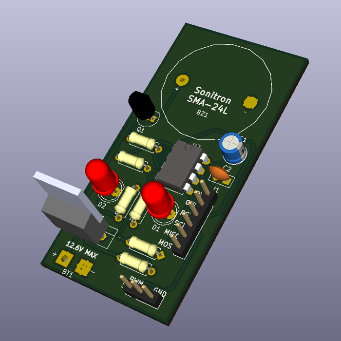
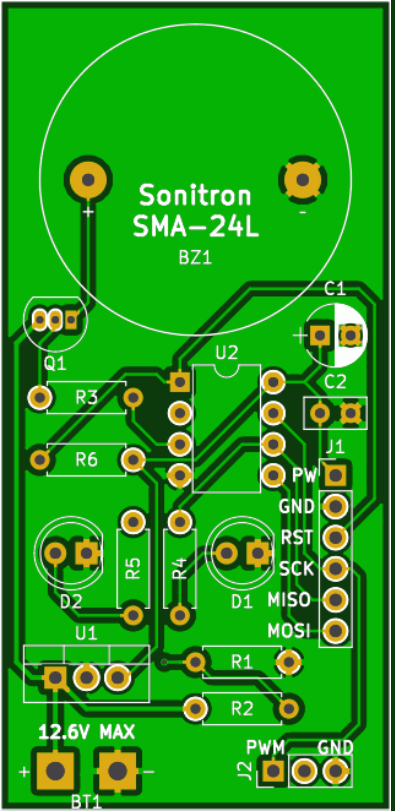
Bill of Material (BoM) & Cost
| Ref | Component | Value / Model | Comment |
| BZ1 | Piezo buzzer | SMA-24L | Sonitron 98dB |
| BT1 | LiPo / LiIon 3S or similar | 12.6V MAX | 4.2V per cell |
| C1 | Electrolytic capacitor | 22µF | dia 5mm, lead space 2.0-2.5mm |
| C2 | Ceramic capacitor | 100nF | lead space 2.0-2.5mm |
| D1 | Red LED | LED | standard 5mm LED |
| D2 | Greed LED | LED | standard 5mm LED |
| J1 | 6 pin header | USBASP | 2.54mm pitch |
| J2 | 3 pic header | PWM | 2.54mm pitch |
| Q1 | NPN Transistor | 2N3904 | TO-92 vertical |
| R1 | Resistor | 10k | 6.3mm |
| R2 | Resistor | 43k | 6.3mm |
| R3 | Resistor | 3k9 | 6.3mm |
| R4 | Resistor | 220R | 6.3mm |
| R5 | Resistor | 220R | 6.3mm |
| R6 | Resistor | 10k | 6.3mm |
| U1 | Voltage regulator | L7805CV (or 78L05) | TO-220 vertical (or TO-92) |
| U2 | Atmel MCU | ATTINY85-20PU | DIP-8 |
Most expensive components are Sonitron SMA-24L piezo buzzer (ca. $6.5) and ATtiny85 MCU (ca. $1.7). I ordered 10 pcs of PCBs and cost of one was $1.5. If you prefer to make PCB on your own, cost would be even lower. Remaining components should not cost more then $2 all together.
Total material cost should not be more than $10-12 (USD).
Technical specification
- micro-controller: ATMEL ATtiny85
- power source: LiIon, LiPo 3S (or similar) – nominal 11.1V (12.6V fully charged)
- PWM: 1000-2000µs (standard servo input)
- recognized PWM ranges:
- LOW: 1000-1249µs (-100%)
- MIDDLE: 1250-1750µs (0%)
- HIGH: 1751-2000µs (+100%)
- maximum battery voltage: 12.6V (4.2V per cell)
- low battery voltage alarm: 9.6V (3.2V per cell)
- critical battery voltage cut-off: 9.0V (3.0V per cell)
- power consumption: 45mA (when both LEDs and Buzzer are on; during normal operation ca. 20mA; in deep sleep mode ca. 10mA)
Safety warning
The MRCMF is not providing protection against deep battery discharge. Some of its features can signal or slow the discharge down, but eventually the battery will get discharged if left for longer time. Some battery types (i.e. LiPo) can be extremely dangerous when discharged below certain level. In worse case scenario they can get fire and cause damage to people or property.
Use the MRCMF at your own risk and responsibility.
How to build your own MRCMF?
- Download Gerber files and firmware HEX file.
- Order or make your own PCB.
- Solder all components (except LEDs).
- Flash the MCU with the firmware. Standard micro-controller programming tools are required to flash the firmware, i.e. USBasp and AVRdude (this is not Atmel MCU programming tutorial, so I will skip this part – tons of tutorials are available on the Internet).
- Solder LEDs (it is better to solder them at the end, as ISP lines are not separated, so you could have issues with flashing the firmware).
- Connect battery and PWM input from your RC receiver.
- Calibrate the battery.
- Program your radio so the MRCMF will be armed and disarmed with the engine of your model. Possibly setup one of switches to trigger the alarm manually.
Downloads
License & Legal disclaimer

This work is licensed under a Creative Commons Attribution-NonCommercial-ShareAlike 4.0 International License.
The project is tested and it worked for me. However there is absolutely no guarantee nor liability behind – use on your own risk and responsibility.
Feedback
Would love to hear your feedback on this project. Let me know if you have build one. Do not hesitate to ask questions if you have any.
Please leave your comments and questions below.