
It is important to take care of harmful fumes when soldering electronics. Using an extractor or even simple fan blowing the fumes away is a great idea. There are many commercial fume extractor available, but it is so much more fun to build DIY one.
Also DIY version allows to choose top quality, quiet and effective fan, like Noctua NF-F12 PWM – which is not always the case with commercial products (they often use cheap and therefore loud fans).
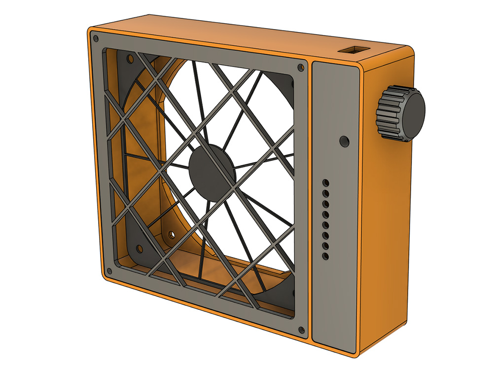
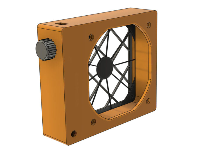
Here is MAK Solder Fume Extractor, feel free to construct your own.
This project is build around the Noctua NF-F12 PWM fan and popular Arduino Nano board. All components are connected more or less on wires, except for LED strip which is soldered on 2x8cm universal PCB prototype board (standard 2.54mm pitch).
Photo Gallery


Bill of Material (BoM)
- Noctua NF-F12 PWM fan
or similar 120x120x25mm fan, with 105mm holes distance (holes 4mm) - Arduino Nano
- 1 x potentiometer (5-10kΩ or similar will do)
- 1 x 5mm LED + 1 x 820Ω for power-on indicator
- 8 x 3mm LEDs + 8 x 620Ω resistors for LED strip
- power-on switch (8.5mm x 14.0mm square mounting)*
- 12V DC power socket (8mm round mounting)*
- 4 x threaded M3 inserts (any length really) + 4 x M3 screws (6-12mm long will do) – to fix the intake grid
- 4 x M4 x 30mm screws and nuts – to fix the fan in the casing
*) There is universal case STL available, with plain 5/6mm round mounting holes for power switch and socket respectively. The universal case allows to use popular range of switches / sockets and it is easy to make mounting holes larger if needed, by simply drilling them out.
You will also need 13x13cm and up to 1cm thick active carbon filter. These are available as large sheets to cut out as needed (i.e. filters for air conditioning units or ready to use fume extractor filters).
The main cost is Noctua fan (around 22 USD), Arduino Nano and other components should not add more than 8 USD, making total cost of around 30 USD. Of course this cost may be cut down significantly by using less expensive fan.
3D Printed Files
STL files are available for download here – https://www.printables.com/model/905050-mak-solder-fume-extractor

Electronics
Very simple design, using widely available Arduino Nano as a controller. Here is the Arduino style schematic:
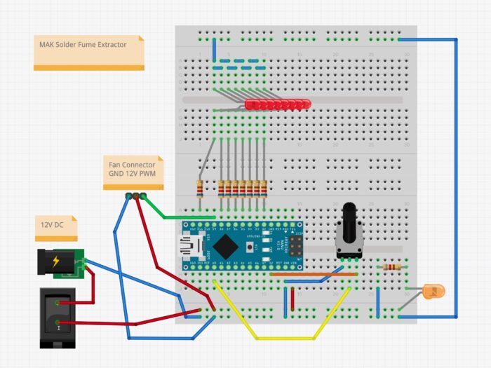
The schematic is pretty straight forward, so no special commentary needed. Please keep in mind that the fan is powered by 12V DC, but the PWM signal must be max. 5V (connecting 12V to PWM input will damage the fan). Arduino Nano is generating 5V outputs, so we are safe here.
Noctua has provided an excellent documentation for the fan, available here – https://www.noctua.at/pub/media/wysiwyg/Noctua_PWM_specifications_white_paper.pdf
The below image shows Noctua PWM connector wire colors (from the above PDF):
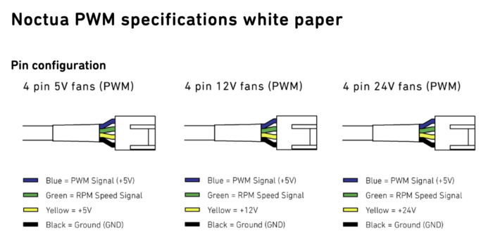
(please note that other vendors may have different standards)
LED limiting current resistors from the Bill of Material are selected to have a dim lights. Choose different ones to your likening and LED colors, but keep in mind Arduino current output limits.
Assembly
The fan if fixed in the case with M4 screws and nuts. Intake grid uses four M3 screws. LED panel (and optionally the LEDs itself) should be glued-in with acrylic (super-glue) or epoxy. PCBs behind the LED panel can be fixed with hot-glue.
Code
The below Arduino sketch is very simple. The only challenge (not really) was to reduce PWM frequency to 25kHz, as required by standard PC fans. Other than that the program reads the potentiometer and sets the output PWM and the LED strip accordingly. The minimum fan speed is fixed to 30%.
// Pins for fan and potentiometer
// (second fan not used)
#define FANPWM1 9
#define FANPWM2 10 // not used in this project
#define POT A0

// Eight LED strip - digital pin numbers in ascending order
int LEDstrip[] = { 2, 3, 4, 5, 6, 7, 8, 11 };

// Global variables
int in, in_prev, out, out_ledstrip, out_ledstrip_prev;

// PWM output @ 25 kHz, on pins 9 and 10 only
// (second parameter is in percent 0-100%)
void analogWrite25k(int pin, int percent) {

    int value = map(percent, 0, 100, 0, 320);

    switch (pin) {
        case FANPWM1:
            OCR1A = value;
            break;
        case FANPWM2:
            OCR1B = value;
            break;
        default:
            // any other pin is not supported
            break;
    }
}

// Update LED strip
// (parameter is in percent 0-100%)
void updateLEDstrip(int percent) {

    for (int i=0; i<8; i++) {
       digitalWrite(LEDstrip[i], LOW);
    }

    int value = map(percent, 0, 100, 0, 7);
    for (int i=0; i<=value; i++) {
       digitalWrite(LEDstrip[i], HIGH);
  }
}

void setup()
{

    // Configure Timer1 for PWM @ 25 kHz
    TCCR1A = 0;           // initialize timer registers
    TCCR1B = 0;
    TCNT1  = 0;
    TCCR1A = _BV(COM1A1)  // non-inverted PWM on channels A and B
           | _BV(COM1B1)
           | _BV(WGM11);  // phase correct PWM, TOP = ICR1 (mode 10)
    TCCR1B = _BV(WGM13)
           | _BV(CS10);   // prescaler 1
    ICR1   = 320;         // top 320

    // Set PWM pins as output
    pinMode(FANPWM1, OUTPUT);
    pinMode(FANPWM2, OUTPUT);

    // Set LED strip as output and run the strip up and down once
    int time = 20;
    for (int i=0; i<8; i++) {
      pinMode(LEDstrip[i], OUTPUT);
      digitalWrite(LEDstrip[i],HIGH);
      delay(time);
    }
    delay(time*25);
    for (int i=7; i>=0; i--) {
      pinMode(LEDstrip[i], OUTPUT);
      digitalWrite(LEDstrip[i],LOW);
      delay(time);
    }
    delay(time*50);

    // Initialize global variables
    in_prev = -1; // to make sure the next loop will be the updating one
    out_ledstrip_prev = -1;
}

void loop() {

    // Read the potentiometer
    in = analogRead(POT);

    // Detect change of the input, act only if potentiometer was changed
    if (in != in_prev) {

        // Update previous value to detect next change
        in_prev = in;

        // Update PWM output
        out = map(in, 0, 1023, 30, 100);   // out maps to 30-100%, so minimum out is 30%
        analogWrite25k(FANPWM1, out);

        // Update LED strip output if it has changed
        out_ledstrip = map(in, 0, 1023, 0, 100);
        if (out_ledstrip != out_ledstrip_prev) {
            // LED strip is different than previous state, let update
            // (that way we avoid flickering, as update per every pot change would be too often)
            out_ledstrip_prev = out_ledstrip;
            updateLEDstrip(out_ledstrip);
        }
    }

}
License & Legal disclaimer

This work is licensed under a Creative Commons Attribution-NonCommercial-NoDerivs 4.0 International License.
The project is tested and it worked for me. However there is absolutely no guarantee nor liability behind – use on your own risk and responsibility.
Feedback
Would love to hear your feedback on this project. Let me know if you have build one. Do not hesitate to ask questions if you have any.
Please leave your comments and questions below.
If you like the project you may consider buying me a coffee.